AUTOMOTIVE ELECTRICIANS PORTAL

Wiring diagrams AUDI 2.0l diesel engine , CGLC,CGLD,CJCA,CJCB,CJCC,CJCD,CMFA

Wiring diagrams AUDI 2.0l diesel engine , CGLC,CGLD,CJCA,CJCB,CJCC,CJCD,CMFA From November 2011

Audi A4 Current Flow Diagram No.  116 / 1
04.2013
Audi A4 Current Flow Diagram No.  116 / 2
Wiring diagrams AUDI 
2.0l diesel engine , CGLC,CGLD,CJCA,CJCB,CJCC,CJCD,CMFA https://portal-diagnostov.com/license.html
https://portal-diagnostov.com/license.html Automotive Electricians Portal FZCO Automotive Electricians Portal FZCO
Download PDF file
ws = white
sw = black
ro = red
rt = red
br = brown
gn = green
bl = blue
gr = grey
li = purple
vi = purple
ge = yellow
or = orange
rs = pink


Battery, Terminal 15 voltage supply relay
A -   BatteryA005A4200805#BTA
J329 -   Terminal 15 voltage supply relayA005A4200803#BTJ329
J367 -   Battery monitor control unitA005A4200805#BTJ367
J393 -   Convenience system central control unitA005A4200805#BTJ393
T2x -   2-pin connectorA005A4200805#BTT2x
T32d -   32-pin connectorA005A4200805#BTT32d
  624 -   Earth point, starter batteryA005A4200801#VB624
  B299 -   Positive connection 3 (30), in main wiring harness
  B300 -   Positive connection 4 (30), in main wiring harness
  B492 -   Positive connection 3 (15), in interior wiring harness

Audi A4 Current Flow Diagram No.  116 / 3
https://portal-diagnostov.com/license.html
https://portal-diagnostov.com/license.html Automotive Electricians Portal FZCO Automotive Electricians Portal FZCO
Get access to all wiring diagrams of the carDownload PDF file
ws = white
sw = black
ro = red
rt = red
br = brown
gn = green
bl = blue
gr = grey
li = purple
vi = purple
ge = yellow
or = orange
rs = pink


Battery isolation igniter, Terminal 30 wiring junction 2
C24 -   Suppression filter
J234 -   Airbag control unitA005A4200805#BTJ234
N253 -   Battery isolation igniterA005A4200802#BTN253
SA2 -   Fuse 2 in fuse holder AA005A4200802#BTSA-
T2y -   2-pin connector
TV22 -   Terminal 30 wiring junction 2
T100 -   100-pin connectorA005A4200805#BTT100
  131 -   Earth connection 2, in engine compartment wiring harness
  500 -   Threaded connection 1 (30), on relay plateA005A4200806#VB500
  501 -   Threaded connection 2 (30), on relay plateA005A4200806#VB501
  A32 -   Positive connection (30), in dash panel wiring harness
  B299 -   Positive connection 3 (30), in main wiring harness
  D50 -   Positive connection (30), in engine compartment wiring harness
  D75 -   Positive connection 2 (30), in engine compartment wiring harness

Audi A4 Current Flow Diagram No.  116 / 4
https://portal-diagnostov.com/license.html
https://portal-diagnostov.com/license.html Automotive Electricians Portal FZCO Automotive Electricians Portal FZCO
Get access to all wiring diagrams of the carDownload PDF file
ws = white
sw = black
ro = red
rt = red
br = brown
gn = green
bl = blue
gr = grey
li = purple
vi = purple
ge = yellow
or = orange
rs = pink


Starter, Alternator, Voltage regulator, Terminal 30 wiring junction 2, Jump start socket
B -   Starter
C -   Alternator
C1 -   Voltage regulator
J500 -   Power steering control unit
S204 -   Fuse 1 (30)A005A4200802#BTS204
S205 -   Fuse 2 (30)A005A4200802#BTS205
S206 -   Fuse 3 (30)
T2n -   2-pin connector
T17e -   17-pin connector, redA005A4200806#BTT17e
T17r -   17-pin connector, whiteA005A4200806#BTT17r
TV22 -   Terminal 30 wiring junction 2
U6 -   Jump start socket
  131 -   Earth connection 2, in engine compartment wiring harness
  A52 -   Positive connection 2 (30), in dash panel wiring harness
  B698 -   Connection 3 (LIN bus) in main wiring harness
* -   see applicable current flow diagram for radiator fan

Audi A4 Current Flow Diagram No.  116 / 5
https://portal-diagnostov.com/license.html
https://portal-diagnostov.com/license.html Automotive Electricians Portal FZCO Automotive Electricians Portal FZCO
Get access to all wiring diagrams of the carDownload PDF file
ws = white
sw = black
ro = red
rt = red
br = brown
gn = green
bl = blue
gr = grey
li = purple
vi = purple
ge = yellow
or = orange
rs = pink


Terminal 30 voltage supply relay, Engine control unit
J317 -   Terminal 30 voltage supply relayA005A4200803#BTJ317
J623 -   Engine control unitA005A4200804#BTJ623
T17q -   17-pin connector, redA005A4200806#BTT17q
T94 -   94-pin connectorA005A4200804#BTT94
  131 -   Earth connection 2, in engine compartment wiring harness
  B146 -   Positive connection 1 (87), in interior wiring harness
  D101 -   Connection 1 in engine compartment wiring harness
  D102 -   Connection 2 in engine compartment wiring harness

Audi A4 Current Flow Diagram No.  116 / 6
https://portal-diagnostov.com/license.html
https://portal-diagnostov.com/license.html Automotive Electricians Portal FZCO Automotive Electricians Portal FZCO
Get access to all wiring diagrams of the carDownload PDF file
ws = white
sw = black
ro = red
rt = red
br = brown
gn = green
bl = blue
gr = grey
li = purple
vi = purple
ge = yellow
or = orange
rs = pink


Starter motor relay, Engine control unit, Starter motor relay 2
J53 -   Starter motor relayA005A4200803#BTJ53
J393 -   Convenience system central control unitA005A4200805#BTJ393
J500 -   Power steering control unit
J532 -   Voltage stabiliserA005A4200805#BTJ532
J623 -   Engine control unitA005A4200804#BTJ623
J695 -   Starter motor relay 2A005A4200803#BTJ695
SB1 -   Fuse 1 on fuse holder BA005A4200802#BTSB-
ST1 -   Fuse carrier 1
SB3 -   Fuse 3 on fuse holder BA005A4200802#BTSB-
SB9 -   Fuse 9 on fuse holder BA005A4200802#BTSB-
SB12 -   Fuse 12 on fuse holder BA005A4200802#BTSB-
SB15 -   Fuse 15 on fuse holder BA005A4200802#BTSB-
T1 -   Single connector
T5l -   5-pin connector, in engine compartment
T6h -   6-pin connector
T12aa -   12-pin connectorA005A4200805#BTT12aa
T17q -   17-pin connector, redA005A4200806#BTT17q
T17r -   17-pin connector, whiteA005A4200806#BTT17r
T32d -   32-pin connectorA005A4200805#BTT32d
T94 -   94-pin connectorA005A4200804#BTT94
  131 -   Earth connection 2, in engine compartment wiring harness
  D51 -   Positive connection 1 (15), in engine compartment wiring harness
  D97 -   Connection (50), in engine compartment right wiring harness
  D210 -   Connection (50), in engine compartment wiring harness
* -   Only models with start/stop system
*2 -   see applicable current flow diagram
*3 -   see applicable current flow diagram for gearbox
*4 -   see applicable current flow diagram for automatic gearbox

Audi A4 Current Flow Diagram No.  116 / 7
https://portal-diagnostov.com/license.html
https://portal-diagnostov.com/license.html Automotive Electricians Portal FZCO Automotive Electricians Portal FZCO
Get access to all wiring diagrams of the carDownload PDF file
ws = white
sw = black
ro = red
rt = red
br = brown
gn = green
bl = blue
gr = grey
li = purple
vi = purple
ge = yellow
or = orange
rs = pink


Automatic glow period control unit, Engine control unit
J179 -   Automatic glow period control unitA005A4200803#BTJ179
J623 -   Engine control unitA005A4200804#BTJ623
Q10 -   Glow plug 1
Q11 -   Glow plug 2
Q12 -   Glow plug 3
Q13 -   Glow plug 4
ST1 -   Fuse carrier 1
SB4 -   Fuse 4 on fuse holder BA005A4200802#BTSB-
SB6 -   Fuse 6 on fuse holder BA005A4200802#BTSB-
S39 -   Engine glow plug strip fuseA005A4200802#BTS39
T94 -   94-pin connectorA005A4200804#BTT94
  12 -   Earth point, on left in engine compartmentA005A4200801#VB12
  85 -   Earth connection 1, in engine compartment wiring harness
  131 -   Earth connection 2, in engine compartment wiring harness
  D103 -   Connection 3 in engine compartment wiring harness

Audi A4 Current Flow Diagram No.  116 / 8
https://portal-diagnostov.com/license.html
https://portal-diagnostov.com/license.html Automotive Electricians Portal FZCO Automotive Electricians Portal FZCO
Get access to all wiring diagrams of the carDownload PDF file
ws = white
sw = black
ro = red
rt = red
br = brown
gn = green
bl = blue
gr = grey
li = purple
vi = purple
ge = yellow
or = orange
rs = pink


Oil level and oil temperature sender, Engine control unit, Climatronic coolant shut-off valve, Coolant circulation pump, Pump for exhaust gas recirculation cooler
G266 -   Oil level and oil temperature sender
J255 -   Climatronic control unitA005A4200805#BTJ255
J623 -   Engine control unitA005A4200804#BTJ623
N422 -   Climatronic coolant shut-off valve
ST1 -   Fuse carrier 1
SB2 -   Fuse 2 on fuse holder BA005A4200802#BTSB-
SB11 -   Fuse 11 on fuse holder BA005A4200802#BTSB-
SB14 -   Fuse 14 on fuse holder BA005A4200802#BTSB-
T5l -   5-pin connector, in engine compartment
T17b -   17-pin connector, blueA005A4200806#BTT17b
T17q -   17-pin connector, redA005A4200806#BTT17q
T20e -   20-pin connectorA005A4200805#BTT20e
T60 -   60-pin connectorA005A4200804#BTT60
T94 -   94-pin connectorA005A4200804#BTT94
V50 -   Coolant circulation pump
V400 -   Pump for exhaust gas recirculation cooler
  85 -   Earth connection 1, in engine compartment wiring harness
  B536 -   Connection 27, in main wiring harness
  D113 -   Connection 11 in engine compartment wiring harness
* -   see applicable current flow diagram for radiator fan
*2 -   see applicable current flow diagram for air conditioning

Audi A4 Current Flow Diagram No.  116 / 9
https://portal-diagnostov.com/license.html
https://portal-diagnostov.com/license.html Automotive Electricians Portal FZCO Automotive Electricians Portal FZCO
Get access to all wiring diagrams of the carDownload PDF file
ws = white
sw = black
ro = red
rt = red
br = brown
gn = green
bl = blue
gr = grey
li = purple
vi = purple
ge = yellow
or = orange
rs = pink


Engine control unit, Charge pressure control solenoid valve, Heater element for crankcase breather, Left electrohydraulic engine mounting solenoid valve, Air filter bypass flap valve, Exhaust gas recirculation cooler changeover valve
J623 -   Engine control unitA005A4200804#BTJ623
J696 -   Gearbox cooling circuit relayA005A4200803#BTJ696
N75 -   Charge pressure control solenoid valve
N79 -   Heater element for crankcase breather
N144 -   Left electrohydraulic engine mounting solenoid valve
N275 -   Air filter bypass flap valve
N345 -   Exhaust gas recirculation cooler changeover valve
N488 -   Coolant valve for gearbox
T60 -   60-pin connectorA005A4200804#BTT60
T94 -   94-pin connectorA005A4200804#BTT94
  85 -   Earth connection 1, in engine compartment wiring harness
  D110 -   Connection 8 in engine compartment wiring harness
* -   Only models with crankcase breather heater element
*2 -   Only models with manual gearbox
*3 -   Cross section depends on equipment

Audi A4 Current Flow Diagram No.  116 / 10
https://portal-diagnostov.com/license.html
https://portal-diagnostov.com/license.html Automotive Electricians Portal FZCO Automotive Electricians Portal FZCO
Get access to all wiring diagrams of the carDownload PDF file
ws = white
sw = black
ro = red
rt = red
br = brown
gn = green
bl = blue
gr = grey
li = purple
vi = purple
ge = yellow
or = orange
rs = pink


Low heat output relay, High heat output relay, Engine control unit, Auxiliary air heater element
J359 -   Low heat output relayA005A4200803#BTJ359
J360 -   High heat output relayA005A4200803#BTJ360
J623 -   Engine control unitA005A4200804#BTJ623
ST1 -   Fuse carrier 1
SB16 -   Fuse 16 on fuse holder BA005A4200802#BTSB-
S126 -   Auxiliary heater fuseA005A4200802#BTS126
S328 -   Auxiliary heater fuse 2A005A4200802#BTS328
T17b -   17-pin connector, blueA005A4200806#BTT17b
T17q -   17-pin connector, redA005A4200806#BTT17q
T94 -   94-pin connectorA005A4200804#BTT94
Z35 -   Auxiliary air heater element
  688 -   Earth point 2, on centre tunnelA005A4200801#VB688
  A138 -   Connection 2, in dash panel wiring harness
  D110 -   Connection 8 in engine compartment wiring harness
  L81 -   Connection in supplementary heater wiring harness
* -   Only models with auxiliary air heater

Audi A4 Current Flow Diagram No.  116 / 11
https://portal-diagnostov.com/license.html
https://portal-diagnostov.com/license.html Automotive Electricians Portal FZCO Automotive Electricians Portal FZCO
Get access to all wiring diagrams of the carDownload PDF file
ws = white
sw = black
ro = red
rt = red
br = brown
gn = green
bl = blue
gr = grey
li = purple
vi = purple
ge = yellow
or = orange
rs = pink


Accelerator position sender, Accelerator position sender 2, Engine control unit
G79 -   Accelerator position sender
G185 -   Accelerator position sender 2
J623 -   Engine control unitA005A4200804#BTJ623
T6ag -   6-pin connector
T17e -   17-pin connector, redA005A4200806#BTT17e
T17r -   17-pin connector, whiteA005A4200806#BTT17r
T94 -   94-pin connectorA005A4200804#BTT94

Audi A4 Current Flow Diagram No.  116 / 12
https://portal-diagnostov.com/license.html
https://portal-diagnostov.com/license.html Automotive Electricians Portal FZCO Automotive Electricians Portal FZCO
Get access to all wiring diagrams of the carDownload PDF file
ws = white
sw = black
ro = red
rt = red
br = brown
gn = green
bl = blue
gr = grey
li = purple
vi = purple
ge = yellow
or = orange
rs = pink


Engine speed sender, Hall sender, Fuel pressure sender, Brake servo pressure sensor, Engine control unit
G28 -   Engine speed sender
G40 -   Hall sender
G247 -   Fuel pressure sender
G294 -   Brake servo pressure sensor
J623 -   Engine control unitA005A4200804#BTJ623
T60 -   60-pin connectorA005A4200804#BTT60
  220 -   Earth connection (sender earth), in engine wiring harness
  327 -   Earth connection (sender earth), in engine compartment wiring harness
  D106 -   Connection 4 in engine compartment wiring harness
  D107 -   Connection 5 in engine compartment wiring harness

Audi A4 Current Flow Diagram No.  116 / 13
https://portal-diagnostov.com/license.html
https://portal-diagnostov.com/license.html Automotive Electricians Portal FZCO Automotive Electricians Portal FZCO
Get access to all wiring diagrams of the carDownload PDF file
ws = white
sw = black
ro = red
rt = red
br = brown
gn = green
bl = blue
gr = grey
li = purple
vi = purple
ge = yellow
or = orange
rs = pink


Throttle valve potentiometer, Fuel temperature sender, Exhaust gas recirculation potentiometer, Position sender for charge pressure positioner, Throttle valve module, Engine control unit, Exhaust gas recirculation control motor
G69 -   Throttle valve potentiometer
G81 -   Fuel temperature sender
G212 -   Exhaust gas recirculation potentiometer
G581 -   Position sender for charge pressure positioner
J338 -   Throttle valve module
J623 -   Engine control unitA005A4200804#BTJ623
T60 -   60-pin connectorA005A4200804#BTT60
V338 -   Exhaust gas recirculation control motor
  220 -   Earth connection (sender earth), in engine wiring harness
  D107 -   Connection 5 in engine compartment wiring harness

Audi A4 Current Flow Diagram No.  116 / 14
https://portal-diagnostov.com/license.html
https://portal-diagnostov.com/license.html Automotive Electricians Portal FZCO Automotive Electricians Portal FZCO
Get access to all wiring diagrams of the carDownload PDF file
ws = white
sw = black
ro = red
rt = red
br = brown
gn = green
bl = blue
gr = grey
li = purple
vi = purple
ge = yellow
or = orange
rs = pink


Charge pressure sender, Intake air temperature sender, Pressure differential sender, Gear detection sensor, Engine control unit
G31 -   Charge pressure sender
G42 -   Intake air temperature sender
G505 -   Pressure differential sender
G604 -   Gear detection sensor
J623 -   Engine control unitA005A4200804#BTJ623
T94 -   94-pin connectorA005A4200804#BTT94
  201 -   Earth connection 5, in engine compartment wiring harness
  D108 -   Connection 6 in engine compartment wiring harness
* -   Only models with manual gearbox
*2 -   From May 2012
*3 -   Gradually discontinued
*4 -   Only models with automatic gearbox

Audi A4 Current Flow Diagram No.  116 / 15
https://portal-diagnostov.com/license.html
https://portal-diagnostov.com/license.html Automotive Electricians Portal FZCO Automotive Electricians Portal FZCO
Get access to all wiring diagrams of the carDownload PDF file
ws = white
sw = black
ro = red
rt = red
br = brown
gn = green
bl = blue
gr = grey
li = purple
vi = purple
ge = yellow
or = orange
rs = pink


Air mass meter, Engine control unit, Fuel pressure regulating valve, Fuel metering valve
G70 -   Air mass meter
J623 -   Engine control unitA005A4200804#BTJ623
N276 -   Fuel pressure regulating valve
N290 -   Fuel metering valve
ST1 -   Fuse carrier 1
SB5 -   Fuse 5 on fuse holder BA005A4200802#BTSB-
SB7 -   Fuse 7 on fuse holder BA005A4200802#BTSB-
T60 -   60-pin connectorA005A4200804#BTT60
T94 -   94-pin connectorA005A4200804#BTT94
  D111 -   Connection 9 in engine compartment wiring harness
* -   Cross section depends on equipment

Audi A4 Current Flow Diagram No.  116 / 16
https://portal-diagnostov.com/license.html
https://portal-diagnostov.com/license.html Automotive Electricians Portal FZCO Automotive Electricians Portal FZCO
Get access to all wiring diagrams of the carDownload PDF file
ws = white
sw = black
ro = red
rt = red
br = brown
gn = green
bl = blue
gr = grey
li = purple
vi = purple
ge = yellow
or = orange
rs = pink


Coolant temperature sender, Radiator outlet coolant temperature sender, Exhaust gas temperature sender 1, Exhaust gas temperature sender 3, Exhaust gas temperature sender 4, Engine control unit
G62 -   Coolant temperature sender
G83 -   Radiator outlet coolant temperature sender
G235 -   Exhaust gas temperature sender 1
G495 -   Exhaust gas temperature sender 3
G648 -   Exhaust gas temperature sender 4
J623 -   Engine control unitA005A4200804#BTJ623
T60 -   60-pin connectorA005A4200804#BTT60
T94 -   94-pin connectorA005A4200804#BTT94
  167 -   Earth connection 4, in engine compartment wiring harness

Audi A4 Current Flow Diagram No.  116 / 17
https://portal-diagnostov.com/license.html
https://portal-diagnostov.com/license.html Automotive Electricians Portal FZCO Automotive Electricians Portal FZCO
Get access to all wiring diagrams of the carDownload PDF file
ws = white
sw = black
ro = red
rt = red
br = brown
gn = green
bl = blue
gr = grey
li = purple
vi = purple
ge = yellow
or = orange
rs = pink


Lambda probe, Engine control unit
E45 -   Cruise control system switch
G39 -   Lambda probe
J527 -   Steering column electronics control unitA005A4200805#BTJ527
J623 -   Engine control unitA005A4200804#BTJ623
ST1 -   Fuse carrier 1
SB10 -   Fuse 10 on fuse holder BA005A4200802#BTSB-
T6aa -   6-pin connector, black
T16f -   16-pin connector
T17b -   17-pin connector, blueA005A4200806#BTT17b
T17q -   17-pin connector, redA005A4200806#BTT17q
T94 -   94-pin connectorA005A4200804#BTT94
Z19 -   Lambda probe heater
* -   Only models with cruise control system (CCS)

Audi A4 Current Flow Diagram No.  116 / 18
https://portal-diagnostov.com/license.html
https://portal-diagnostov.com/license.html Automotive Electricians Portal FZCO Automotive Electricians Portal FZCO
Get access to all wiring diagrams of the carDownload PDF file
ws = white
sw = black
ro = red
rt = red
br = brown
gn = green
bl = blue
gr = grey
li = purple
vi = purple
ge = yellow
or = orange
rs = pink


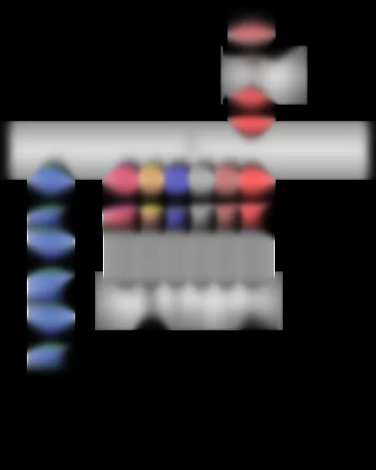
Engine control unit, Injector, cylinder 1, Injector, cylinder 2, Injector, cylinder 3, Injector, cylinder 4
J623 -   Engine control unitA005A4200804#BTJ623
N30 -   Injector, cylinder 1
N31 -   Injector, cylinder 2
N32 -   Injector, cylinder 3
N33 -   Injector, cylinder 4
T60 -   60-pin connectorA005A4200804#BTT60

Audi A4 Current Flow Diagram No.  116 / 19
https://portal-diagnostov.com/license.html
https://portal-diagnostov.com/license.html Automotive Electricians Portal FZCO Automotive Electricians Portal FZCO
Get access to all wiring diagrams of the carDownload PDF file
ws = white
sw = black
ro = red
rt = red
br = brown
gn = green
bl = blue
gr = grey
li = purple
vi = purple
ge = yellow
or = orange
rs = pink


NOx sender 2, Engine control unit, Control unit for NOx sender 2
G687 -   NOx sender 2
J623 -   Engine control unitA005A4200804#BTJ623
J881 -   Control unit for NOx sender 2
N474 -   Injector for reducing agent
ST1 -   Fuse carrier 1
SB8 -   Fuse 8 on fuse holder BA005A4200802#BTSB-
T17q -   17-pin connector, redA005A4200806#BTT17q
T94 -   94-pin connectorA005A4200804#BTT94
  50 -   Earth point, on left in luggage compartmentA005A4200801#VB50
  371 -   Earth connection 6, in main wiring harness
* -   Only models with SCR system

Audi A4 Current Flow Diagram No.  116 / 20
https://portal-diagnostov.com/license.html
https://portal-diagnostov.com/license.html Automotive Electricians Portal FZCO Automotive Electricians Portal FZCO
Get access to all wiring diagrams of the carDownload PDF file
ws = white
sw = black
ro = red
rt = red
br = brown
gn = green
bl = blue
gr = grey
li = purple
vi = purple
ge = yellow
or = orange
rs = pink


Engine control unit, Pump for reducing agent
G686 -   Pressure sender for reducing agent metering system
J623 -   Engine control unitA005A4200804#BTJ623
ST2 -   Fuse carrier 2
SC4 -   Fuse 4 on fuse holder CA005A4200802#BTSC-
T8am -   8-pin connector, black
T8d -   8-pin connector
T8e -   8-pin connector, black
T14k -   14-pin connector, brown
T17t -   17-pin connector, brownA005A4200806#BTT17t
T94 -   94-pin connectorA005A4200804#BTT94
V437 -   Pump for reducing agent
Z103 -   Heater for reducing-agent pump (heater circuit 2)
  209 -   Earth connection 6, in engine compartment wiring harness
  371 -   Earth connection 6, in main wiring harness
  H3 -   Connection 1 in wiring harness for reducing-agent tank
  H4 -   Connection 2 in wiring harness for reducing-agent tank
* -   Only models with SCR system
*2 -   Adapter wire

Audi A4 Current Flow Diagram No.  116 / 21
https://portal-diagnostov.com/license.html
https://portal-diagnostov.com/license.html Automotive Electricians Portal FZCO Automotive Electricians Portal FZCO
Get access to all wiring diagrams of the carDownload PDF file
ws = white
sw = black
ro = red
rt = red
br = brown
gn = green
bl = blue
gr = grey
li = purple
vi = purple
ge = yellow
or = orange
rs = pink


Engine control unit, Control unit for reducing agent metering system
J623 -   Engine control unitA005A4200804#BTJ623
J880 -   Control unit for reducing agent metering system
ST5 -   Fuse carrier 5
SF11 -   Fuse 11 in fuse holder FA005A4200802#BTSF-
T8am -   8-pin connector, black
T14k -   14-pin connector, brown
T17t -   17-pin connector, brownA005A4200806#BTT17t
T30c -   30-pin connector
T94 -   94-pin connectorA005A4200804#BTT94
V436 -   Transfer pump for reducing agent
  51 -   Earth point, on right in luggage compartmentA005A4200801#VB51
  209 -   Earth connection 6, in engine compartment wiring harness
  372 -   Earth connection 7, in main wiring harness
* -   Only models with SCR system
*2 -   see applicable current flow diagram for fuse assignment

Audi A4 Current Flow Diagram No.  116 / 22
https://portal-diagnostov.com/license.html
https://portal-diagnostov.com/license.html Automotive Electricians Portal FZCO Automotive Electricians Portal FZCO
Get access to all wiring diagrams of the carDownload PDF file
ws = white
sw = black
ro = red
rt = red
br = brown
gn = green
bl = blue
gr = grey
li = purple
vi = purple
ge = yellow
or = orange
rs = pink


Engine control unit, Control unit for reducing agent metering system, Heater for reducing-agent tank (heater circuit 1), Heater for reducing-agent line (heater circuit 2)
J623 -   Engine control unitA005A4200804#BTJ623
J880 -   Control unit for reducing agent metering system
T2al -   2-pin connector, brown
T2am -   2-pin connector, orange
T2e -   2-pin connector, black
T2j -   2-pin connector, black
T8am -   8-pin connector, black
T14k -   14-pin connector, brown
T17t -   17-pin connector, brownA005A4200806#BTT17t
T30c -   30-pin connector
T94 -   94-pin connectorA005A4200804#BTT94
Z102 -   Heater for reducing-agent tank (heater circuit 1)
Z104 -   Heater for reducing-agent line (heater circuit 2)
  367 -   Earth connection 2, in main wiring harness
  688 -   Earth point 2, on centre tunnelA005A4200801#VB688
  H5 -   Connection 3 in wiring harness for reducing-agent tank
* -   Only models with SCR system

Audi A4 Current Flow Diagram No.  116 / 23
https://portal-diagnostov.com/license.html
https://portal-diagnostov.com/license.html Automotive Electricians Portal FZCO Automotive Electricians Portal FZCO
Get access to all wiring diagrams of the carDownload PDF file
ws = white
sw = black
ro = red
rt = red
br = brown
gn = green
bl = blue
gr = grey
li = purple
vi = purple
ge = yellow
or = orange
rs = pink


Tank sender for reducing agent, Temperature sender for reducing agent, Engine control unit, Control unit for reducing agent metering system
G684 -   Tank sender for reducing agent
G685 -   Temperature sender for reducing agent
J623 -   Engine control unitA005A4200804#BTJ623
J880 -   Control unit for reducing agent metering system
T2h -   2-pin connector
T4bh -   4-pin connector, black
T8am -   8-pin connector, black
T14k -   14-pin connector, brown
T17t -   17-pin connector, brownA005A4200806#BTT17t
T30c -   30-pin connector
T94 -   94-pin connectorA005A4200804#BTT94
Z107 -   Heater for reducing-agent breather line
  367 -   Earth connection 2, in main wiring harness
  H6 -   Connection 4 in wiring harness for reducing-agent tank
* -   Only models with SCR system

Audi A4 Current Flow Diagram No.  116 / 24
https://portal-diagnostov.com/license.html
https://portal-diagnostov.com/license.html Automotive Electricians Portal FZCO Automotive Electricians Portal FZCO
Get access to all wiring diagrams of the carDownload PDF file
ws = white
sw = black
ro = red
rt = red
br = brown
gn = green
bl = blue
gr = grey
li = purple
vi = purple
ge = yellow
or = orange
rs = pink


Clutch position sender, Engine control unit
F36 -   Clutch pedal switch
F194 -   Clutch pedal switch for engine start
G476 -   Clutch position sender
J540 -   Control unit for electromechanical parking brakeA005A4200805#BTJ540
J623 -   Engine control unitA005A4200804#BTJ623
ST1 -   Fuse carrier 1
SC10 -   Fuse 10 on fuse holder CA005A4200802#BTSC-
SC16 -   Fuse 16 on fuse holder CA005A4200802#BTSC-
T6g -   6-pin connector
T17q -   17-pin connector, redA005A4200806#BTT17q
T30a -   30-pin connector
T94 -   94-pin connectorA005A4200804#BTT94
  370 -   Earth connection 5, in main wiring harness
  639 -   Earth point, left A-pillarA005A4200801#VB639
  B471 -   Connection 7, in main wiring harness
  D114 -   Connection 12 in engine compartment wiring harness
* -   Only models with manual gearbox
*2 -   Only models with automatic gearbox
*3 -   Wiring colour depends on equipment
*4 -   see applicable current flow diagram for automatic gearbox

Audi A4 Current Flow Diagram No.  116 / 25
https://portal-diagnostov.com/license.html
https://portal-diagnostov.com/license.html Automotive Electricians Portal FZCO Automotive Electricians Portal FZCO
Get access to all wiring diagrams of the carDownload PDF file
ws = white
sw = black
ro = red
rt = red
br = brown
gn = green
bl = blue
gr = grey
li = purple
vi = purple
ge = yellow
or = orange
rs = pink


Brake light switch, Oil pressure switch, Engine control unit
F -   Brake light switch
F22 -   Oil pressure switch
J255 -   Climatronic control unitA005A4200805#BTJ255
J623 -   Engine control unitA005A4200804#BTJ623
ST2 -   Fuse carrier 2
SC2 -   Fuse 2 on fuse holder CA005A4200802#BTSC-
T4k -   4-pin connector
T17e -   17-pin connector, redA005A4200806#BTT17e
T17q -   17-pin connector, blackA005A4200806#BTT17q
T17r -   17-pin connector, whiteA005A4200806#BTT17r
T20e -   20-pin connectorA005A4200805#BTT20e
T60 -   60-pin connectorA005A4200804#BTT60
T94 -   94-pin connectorA005A4200804#BTT94
  B335 -   Connection 1 (54), in main wiring harness
* -   Solenoid coil for brake light sensor

Audi A4 Current Flow Diagram No.  116 / 26
https://portal-diagnostov.com/license.html
https://portal-diagnostov.com/license.html Automotive Electricians Portal FZCO Automotive Electricians Portal FZCO
Get access to all wiring diagrams of the carDownload PDF file
ws = white
sw = black
ro = red
rt = red
br = brown
gn = green
bl = blue
gr = grey
li = purple
vi = purple
ge = yellow
or = orange
rs = pink


Data bus diagnostic interface, Engine control unit
J217 -   Automatic gearbox control unitA005A4200804#BTJ217
J533 -   Data bus diagnostic interfaceA005A4200805#BTJ533
J623 -   Engine control unitA005A4200804#BTJ623
J743 -   Mechatronic unit for dual clutch gearboxA005A4200804#BTJ743
T17b -   17-pin connector, blueA005A4200806#BTT17b
T17r -   17-pin connector, whiteA005A4200806#BTT17r
T20d -   20-pin connectorA005A4200805#BTT20d
T94 -   94-pin connectorA005A4200804#BTT94
  B383 -   Connection 1 (powertrain CAN bus, high), in main wiring harness
  B390 -   Connection 1 (powertrain CAN bus, low), in main wiring harness
  D159 -   Connection (high bus), in engine compartment wiring harness
  D160 -   Connection (low bus), in engine compartment wiring harness
* -   Only models with automatic gearbox
*2 -   see applicable current flow diagram for automatic gearbox

Audi A4 Current Flow Diagram No.  116 / 27
https://portal-diagnostov.com/license.html
https://portal-diagnostov.com/license.html Automotive Electricians Portal FZCO Automotive Electricians Portal FZCO
Get access to all wiring diagrams of the carDownload PDF file
ws = white
sw = black
ro = red
rt = red
br = brown
gn = green
bl = blue
gr = grey
li = purple
vi = purple
ge = yellow
or = orange
rs = pink


Control unit in dash panel insert, Data bus diagnostic interface
J285 -   Control unit in dash panel insertA005A4200805#BTJ285
J533 -   Data bus diagnostic interfaceA005A4200805#BTJ533
ST2 -   Fuse carrier 2
SD4 -   Fuse 4 on fuse holder DA005A4200802#BTSD-
SD5 -   Fuse 5 on fuse holder DA005A4200802#BTSD-
T20d -   20-pin connectorA005A4200805#BTT20d
T32f -   32-pin connectorA005A4200805#BTT32f
T46s -   46-pin connectorA005A4200806#BTT46s
  81 -   Earth connection 1, in dash panel wiring harness
  135 -   Earth connection 2, in dash panel wiring harness
  687 -   Earth point 1, on centre tunnelA005A4200801#VB687
* -   see applicable current flow diagram for CAN separating connector
*2 -   see applicable current flow diagram for fuse assignment

Audi A4 Current Flow Diagram No.  116 / 28
https://portal-diagnostov.com/license.html
https://portal-diagnostov.com/license.html Automotive Electricians Portal FZCO Automotive Electricians Portal FZCO
Get access to all wiring diagrams of the carDownload PDF file
ws = white
sw = black
ro = red
rt = red
br = brown
gn = green
bl = blue
gr = grey
li = purple
vi = purple
ge = yellow
or = orange
rs = pink


Fuel delivery unit, Fuel system pressurisation pump, Control unit in dash panel insert, Fuel pump control unit
G -   Fuel gauge sender
GX1 -   Fuel delivery unit
G6 -   Fuel system pressurisation pump
G169 -   Fuel gauge sender 2
J285 -   Control unit in dash panel insertA005A4200805#BTJ285
J538 -   Fuel pump control unitA005A4200805#BTJ538
ST2 -   Fuse carrier 2
SC3 -   Fuse 3 on fuse holder CA005A4200802#BTSC-
T4s -   4-pin connector
T6bl -   6-pin connector
T6r -   6-pin connector
T17f -   17-pin connector, brownA005A4200806#BTT17f
T17g -   17-pin connector, blackA005A4200806#BTT17g
T32f -   32-pin connectorA005A4200805#BTT32f
  369 -   Earth connection 4, in main wiring harness
  730 -   Earth point 1, on right rear wheel housingA005A4200801#VB730
* -   Only models with all-wheel drive

Audi A4 Current Flow Diagram No.  116 / 29
https://portal-diagnostov.com/license.html
https://portal-diagnostov.com/license.html Automotive Electricians Portal FZCO Automotive Electricians Portal FZCO
Get access to all wiring diagrams of the carDownload PDF file
ws = white
sw = black
ro = red
rt = red
br = brown
gn = green
bl = blue
gr = grey
li = purple
vi = purple
ge = yellow
or = orange
rs = pink


Coolant shortage indicator sender, Onboard supply control unit, Air conditioner compressor regulating valve
G32 -   Coolant shortage indicator sender
J519 -   Onboard supply control unitA005A4200805#BTJ519
N280 -   Air conditioner compressor regulating valve
T2t -   2-pin connector
T17l -   17-pin connectorA005A4200805#BTT17l
T17r -   17-pin connector, whiteA005A4200806#BTT17r
T32b -   32-pin connectorA005A4200805#BTT32b
  401 -   Earth connection (sender earth), in interior wiring harness