AIR CONDITIONING
Automatic A/C Wiring Diagram (1 of 2) for Mitsubishi Eclipse Spyder GT 2011
 https://portal-diagnostov.com/license.html
Automotive Electricians Portal FZCO
Automotive Electricians Portal FZCO
https://portal-diagnostov.com/license.html
https://portal-diagnostov.com/license.html
Automotive Electricians Portal FZCO
Automotive Electricians Portal FZCO
List of elements for Automatic A/C Wiring Diagram (1 of 2) for Mitsubishi Eclipse Spyder GT 2011:
- (behind left side of dash)
- A/c ecu (integral to heater control unit)
- A/c pressure sensor (right side of engine compartment)
- Air mixing damper control motor & potentiometer (behind right side of dash)
- Air thermo sensor (behind center of dash, on heater unit)
- Ambient temperature sensor (near lower left side of radiator)
- C15
- C20
- C21
- C24
- Defogger system
- Engine compartment relay box (left side of engine compt)
- Front ecu (in engine compt relay box)
- Fuse 10a
- Fuse 15a
- Fuse 7.5a
- Heater air intake duct sensor (under left side of dash, in air duct)
- Hot at all times
- Hot in acc or on
- Hot w/ taillight relay energized
- Illumination light relay
- Interior lights system
- Joint connector 1 (behind left side of dash)
- Joint connector 2 (behind left side of dash)
- Mode selection damper control motor & potentiometer (behind left side of dash)
- Nca
- Outside/inside air selection damper control motor (behind right side of dash, on hvac unit)
- Red
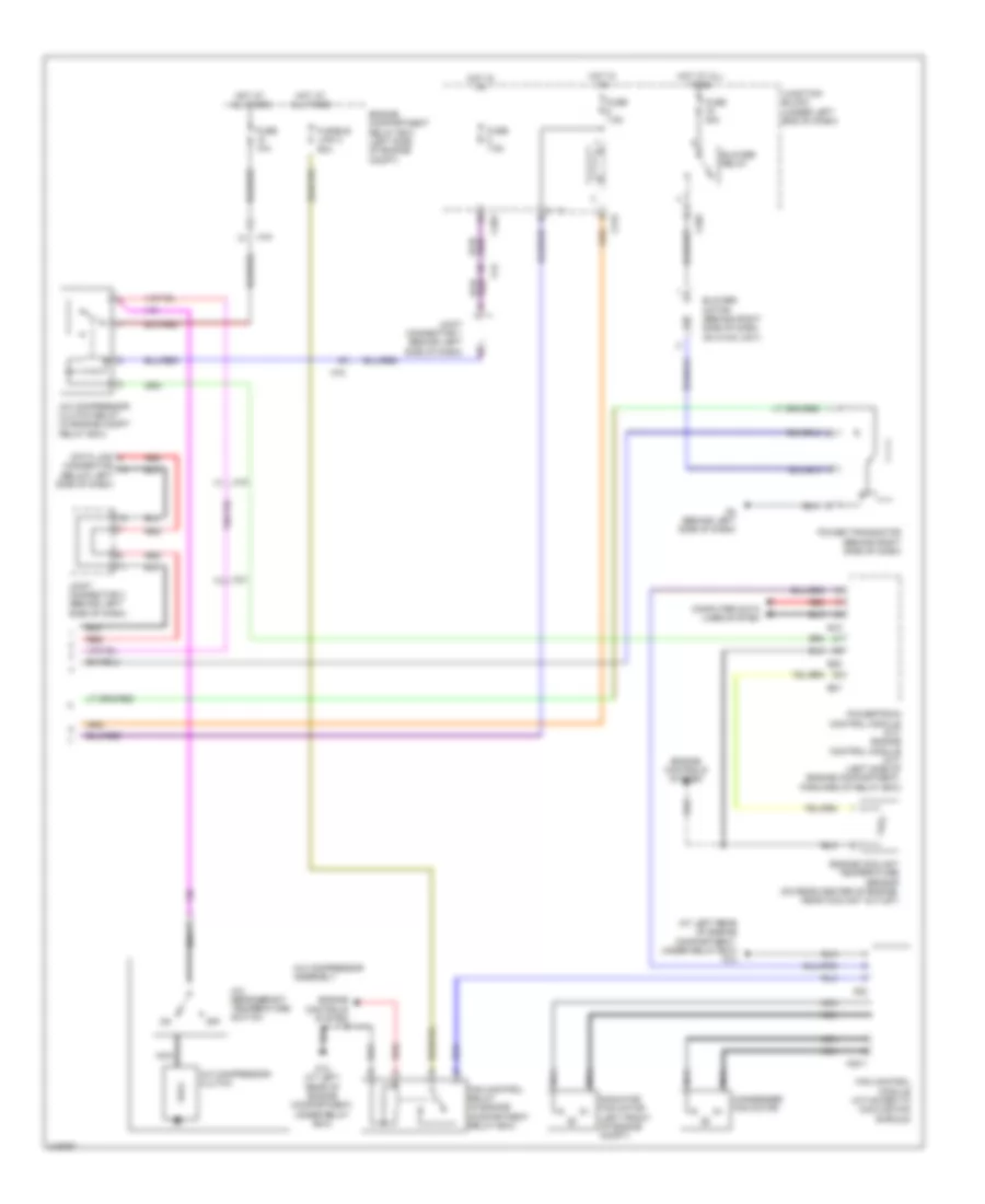
Automatic A/C Wiring Diagram (2 of 2) for Mitsubishi Eclipse Spyder GT 2011
List of elements for Automatic A/C Wiring Diagram (2 of 2) for Mitsubishi Eclipse Spyder GT 2011:
- (at left rear of engine compartment, under relay box) g12
- A/c compressor assembly
- A/c compressor clutch
- A/c compressor clutch relay (in engine compt relay box)
- A/c refrigerant temperature switch
- A15
- A22
- A22-1
- B18
- B20
- B21
- Blower motor (behind right side of dash, on hvac unit)
- Blower relay
- C202
- C203
- C21
- C215
- C24
- Computer data lines system
- Condenser fan motor
- Connector (below left side of dash)
- Data link
- Engine compartment relay box (left side of engine compt)
- Engine controls system
- Engine coolant temperature sensor (on rear center of engine, near coolant outlet)
- Fan control module (attached to cooling fan shroud)
- Fan control relay (in engine compartment relay box)
- Fuse 10a
- Fuse 30a
- Fuse 7.5a
- Fusible link 2 50a
- G12 (at left rear of engine compartment, under relay box)
- G4 (behind left side of dash)
- Hot at all times
- Hot in on
- Joint connector 1 (behind left side of dash)
- Joint connector 3 (behind left side of dash)
- Junction block (under left end of dash)
- Nca
- Off
- Power transistor (behind right side of dash)
- Powertrain control module (a/t) engine control module (m/t) (left side of engine compartment, forward of relay box)
- Radiator fan motor (left front of engine compt)
- Red
Manual A/C Wiring Diagram (1 of 2) for Mitsubishi Eclipse Spyder GT 2011
List of elements for Manual A/C Wiring Diagram (1 of 2) for Mitsubishi Eclipse Spyder GT 2011:
- (at left rear of engine compartment, under relay box) g12
- (behind left side of dash) joint connector 1
- (in engine compt relay box) front ecu
- (left front of engine compt) condenser fan motor
- A/c ecu (integral to heater control unit)
- A/c pressure sensor (right side of engine compartment)
- A15
- Air mixing damper control motor & potentiometer (behind right side of dash)
- Air thermo sensor (behind center of dash, on heater unit)
- Ambient temperature sensor (near lower left side of radiator)
- C14
- C19
- C203
- C21
- C24
- Condenser fan relay (left front of engine compt, in relay box)
- Defogger system
- Engine compartment relay box (left side of engine compt)
- Fan control relay (in engine compt relay box)
- Fuse 10a
- Fuse 15a
- Fuse 7.5a
- Fusible link 2 30a
- Fusible link 26 20a
- G12 (at left rear of engine compartment, under relay box)
- G3 (under center of dash)
- Headlights
- Hot at all times
- Hot in acc or on
- Hot in on
- Hot w/ taillight relay energized
- Illumi- nation light relay
- Interior lights system
- Joint connector 1 (behind left side of dash)
- Joint connector 2 (behind left side of dash)
- Junction block (under left end of dash)
- Mode selection damper control motor & potentiometer (behind left side of dash)
- Nca
- Outside/inside air selection damper control motor (behind right side of dash, on hvac unit)
- Radiator fan motor (left front of engine compt, in relay box)
- Radiator fan relay (left front of engine compt, in relay box)
- Red
- W/ discharge type
- W/ halogen type headlights
Manual A/C Wiring Diagram (2 of 2) for Mitsubishi Eclipse Spyder GT 2011
List of elements for Manual A/C Wiring Diagram (2 of 2) for Mitsubishi Eclipse Spyder GT 2011:
- A/c compressor assembly
- A/c compressor clutch
- A/c compressor clutch relay (in engine compt relay box)
- A/c refrigerant temperature switch
- A15
- B18
- B20
- B21
- Blower motor (behind right side of dash, on hvac unit)
- Blower relay
- Blower switch
- C202
- C215
- Computer data lines system
- Connector (below left side of dash)
- Data link
- Engine compartment relay box (left side of engine compt)
- Engine control module (m/t) powertrain control module (a/t) (left side of engine compartment, forward of relay box)
- Engine controls system
- Engine coolant temperature sensor (on rear of engine, near coolant outlet)
- Fuse 10a
- Fuse 30a
- Fuse 7.5a
- G4 (behind left side of dash)
- Hot at all times
- Hot in on
- Joint connector 2 (behind left side of dash)
- Joint connector 3 (behind left side of dash)
- Junction block (under left end of dash)
- Nca
- Off
- Red
- Resistor (behind right side of dash)

 Čeština
 Dansk
Dansk Deutsch
 Ελληνικά
 English
 Español
 Suomi
Suomi Français
 Français
 עברית
עברית Hrvatski
 Magyar
 Italiano
 日本語
日本語 한국어
한국어 Nederlands
 Polski
 Português
 Português
 Română
 Русский
 Slovenčina
 Slovenščina
 Svenska
 Türkçe
 中文 (中国)