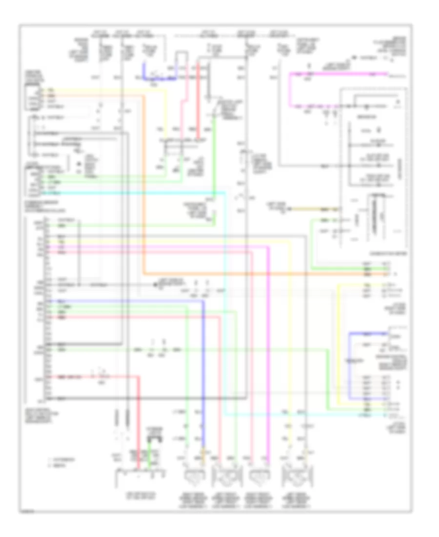
AIR CONDITIONING
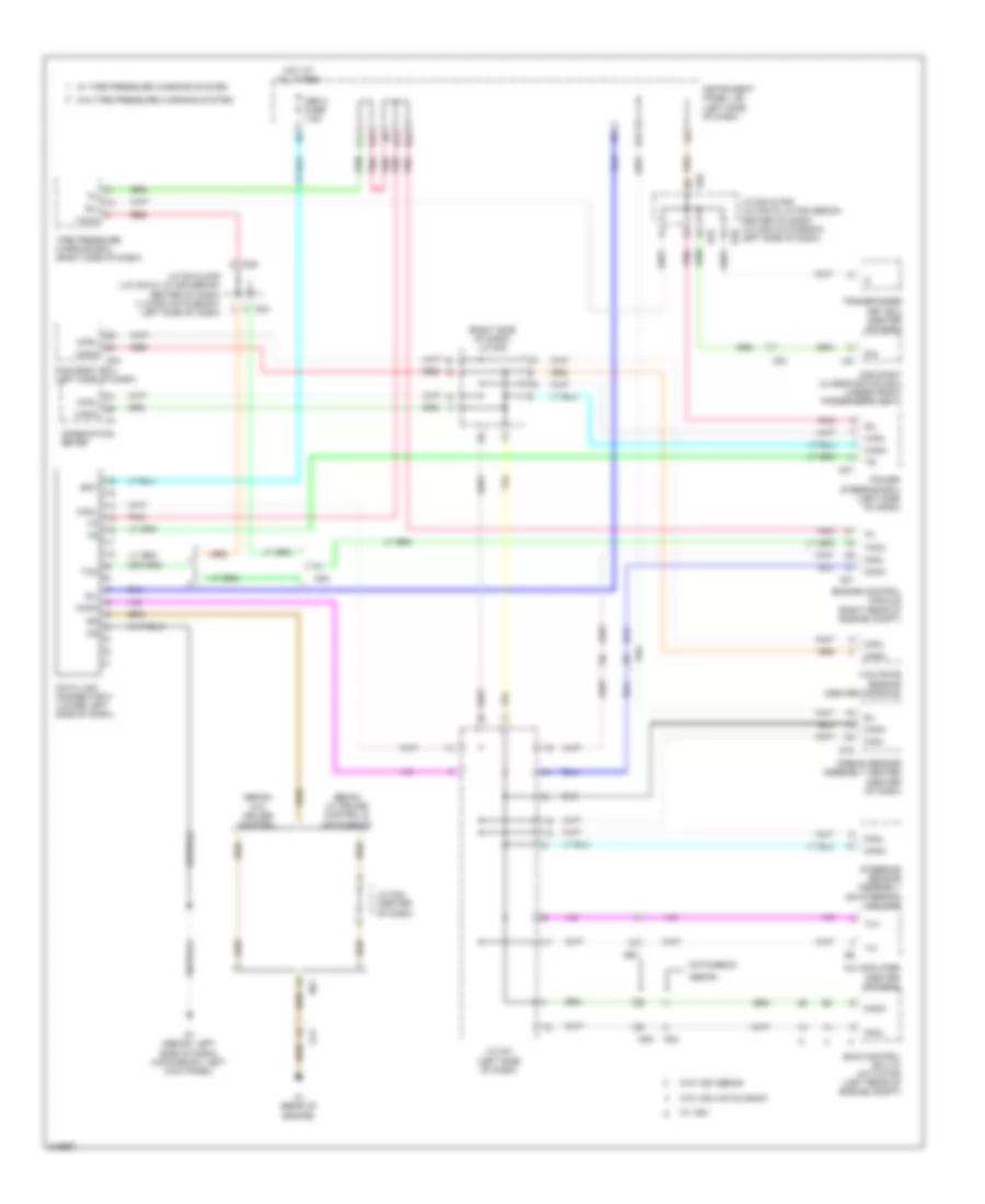
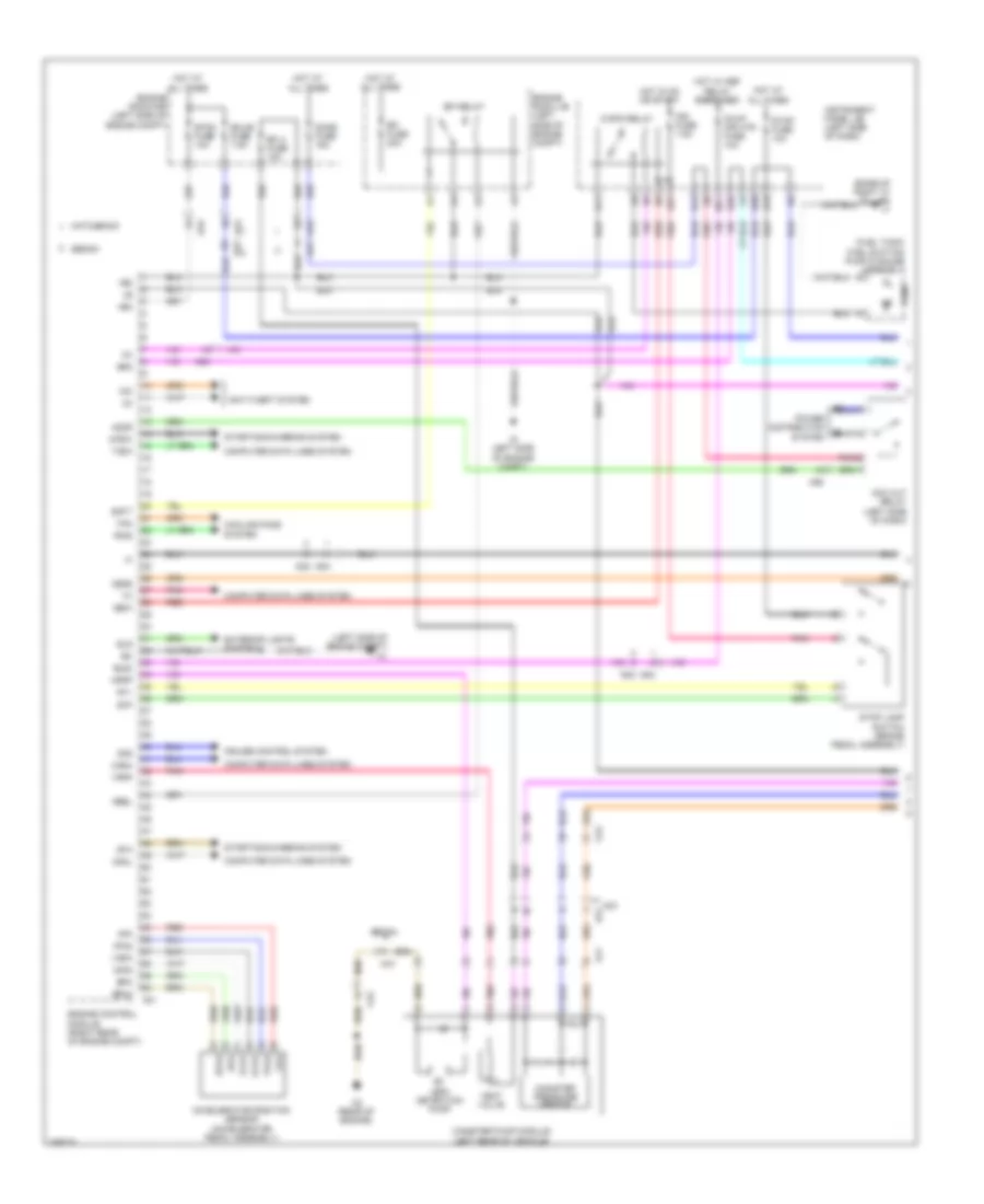
Manual A/C Wiring Diagram (1 of 2) for Toyota Yaris 2011
 https://portal-diagnostov.com/license.html
Automotive Electricians Portal FZCO
Automotive Electricians Portal FZCO
https://portal-diagnostov.com/license.html
https://portal-diagnostov.com/license.html
Automotive Electricians Portal FZCO
Automotive Electricians Portal FZCO
List of elements for Manual A/C Wiring Diagram (1 of 2) for Toyota Yaris 2011:
- (center of dash)
- (left side of dash)
- (left side of engine compt) a1
- (w/ ptc heater) htr sub 1 relay
- (w/ ptc heater) htr sub 3/trk relay
- (w/ ptc heater) htr sub relay 2
- A/c
- A/c amplifier (center of dash)
- A/c compressor (left front of engine)
- A/c pressure sensor (left front of engine)
- A1 (left side of engine compt)
- A21
- Ad4
- Ae1
- Alt
- Ambient temperature sensor (behind front grille)
- B/v
- Ba1
- C20
- Ca1
- Can h
- Can l
- De1
- Engine control module (right rear of engine compt)
- Engine coolant temperature sensor (top rear of engine)
- Engine room r/b (left side of engine compt)
- Engine room r/b 2 (right side of engine compt)
- Ethw
- Fan
- Gnd
- Heat
- Hls
- Hot at all times
- Hrly
- Htr sub 1 fuse 30a
- Htr sub 2 fuse 40a
- Ig+
- J/b 6 (right kick panel)
- J/c a25 (sedan: left side of engine compt)
- J/c d40
- J/c d41
- J/c e10
- Led
- Main body ecu (w/ ptc heater)
- Pnk
- Pre
- Ptc heater (if equipped) (hatchback: left side of dash) (sedan: center of dash)
- Ptc1
- Ptc2
- Ptc3
- Red
- S5-3
- Sblw
- Sg-1
- Sg-2
- Sol +
- Starting/ charging system
- Tam
- Thw
- Tx +
- Tx -
- W/ ptc heater
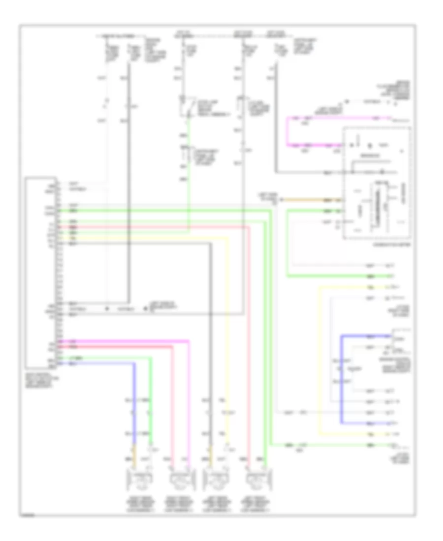
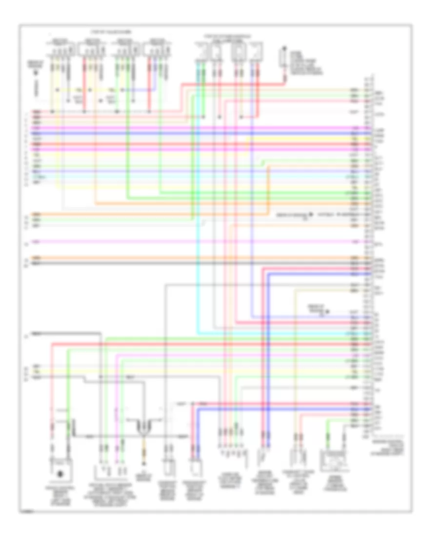
Manual A/C Wiring Diagram (2 of 2) for Toyota Yaris 2011
List of elements for Manual A/C Wiring Diagram (2 of 2) for Toyota Yaris 2011:
- (center of dash)
- (left front of engine compt) radiator fan resistor
- (sedan: left side of engine compt) j/c a25
- (sedan: right side of dash) (hatchback: behind right side of dash) blower motor
- A/c fuse 7.5a
- A/c sw
- A/c switch
- A/c thermistor 1 (center of dash)
- A1 (left side of engine compt)
- Aa2
- B24
- Blower resistor (right side of dash)
- Blower switch
- Cooling fan motor (sedan: center radiator support) (hatchback: center front of engine compt)
- D1 (hatchback: left kick panel) (sedan: left side of dash)
- D2 (right kick panel)
- De1
- Defroster mode detection sw
- E17
- Ecu-ig fuse 10a
- Ed1
- Engine room j/b (left side of engine compt)
- Engine room r/b (left side of engine compt)
- Fan relay 1
- Fan relay 2
- Gauge fuse 10a
- Hot at all times
- Hot in on or start
- Htr fuse 40a
- Htr relay
- Instrument panel j/b (left side of dash)
- J/c e10
- J/c e10 (center of dash)
- Max hot sw
- Off
- Pnk
- Rdi fuse 30a
- Rear window defogger switch
- Red
- S10
- W/ a/c switch
- W/ defroster detection switch & w/ a/c switch
- W/ ptc heater
- W/o a/c switch
- W/o defroster detection switch & w/ a/c switch
- W/o ptc heater
ANTI-LOCK BRAKES
Anti-lock Brakes Wiring Diagram, with VSC for Toyota Yaris 2011
List of elements for Anti-lock Brakes Wiring Diagram, with VSC for Toyota Yaris 2011:
- (brake fluid reservoir) brake fluid level warning switch
- (center console) yaw rate sensor
- (left side of dash) d3
- (left side of engine compt) a2
- (w/ vsc off sw)
- +bm
- +bs
- A1 (left side of engine compt)
- A21
- Aa1
- Aa2
- Abs ind
- Abs1/ vsc1 fuse 50a
- Abs2/ vsc2 fuse 30a
- Ad3
- Ad4
- Aj1
- B12
- B18
- B21
- B24
- B30
- Bat
- Brake ind
- Can controller
- Can i/f
- Canh
- Canl
- Combination meter
- Cpu
- Csw
- D36
- D37
- D76
- Ecu-b fuse 7.5a
- Ecu-ig fuse 10a
- Engine control module (right rear of engine compt)
- Engine room r/b (left side of engine compt)
- Ess
- Fl+
- Fl-
- Fr+
- Fr-
- Gnd
- Gnd1
- Gnd2
- H12
- Hatchback
- Hot at all times
- Hot in on or start
- Ig1
- Ill+
- Ill-
- Instrument panel j/b (left side of dash)
- Interior lights system
- J/b 6 (hatch back: right kick panel)
- J/c a25 (sedan: left side of engine compt)
- J/c d36 & d37 (center of dash)
- J/c d40 (left side of dash)
- J/c d41 (left side of dash)
- J/c d42 (right side of dash)
- Led driver
- Left front speed sensor (left front hub assembly)
- Left rear speed sensor (left rear hub assembly)
- Met fuse 7.5a
- Pnk
- Red
- Right front speed sensor (right front hub assembly)
- Right rear speed sensor (right rear hub assembly)
- Rl+
- Rl-
- Rr+
- Rr-
- Sedan
- Skid control ecu w/ actuator (left rear of engine compt)
- Slip ind
- Slip off ind
- Steering sensor assembly (on steering column)
- Stop fuse 10a
- Stop lamp switch (brake pedal assembly)
- Stp
- Trac off ind
- Vsc off switch (w/ vsc off sw)
- Zj1
Anti-lock Brakes Wiring Diagram, without VSC Hatchback for Toyota Yaris 2011
List of elements for Anti-lock Brakes Wiring Diagram, without VSC Hatchback for Toyota Yaris 2011:
- (brake fluid reservoir) brake fluid level warning switch
- (left side of dash) d3
- (left side of engine compt) a2
- +bm
- +bs
- A1 (left side of engine compt)
- A21
- Abs ind
- Abs1/ vsc1 fuse 50a
- Abs2/ vsc2 fuse 30a
- Ad3
- Aj1
- B12
- B18
- B21
- B24
- Brake ind
- Can controller
- Can i/f
- Canh
- Canl
- Combination meter
- Cpu
- Ecu-ig fuse 10a
- Engine control module (right rear of engine compt)
- Engine room r/b (left side of engine compt)
- Fl+
- Fl-
- Fr+
- Fr-
- Gnd1
- Gnd2
- Hot at all times
- Hot in on or start
- Ig1
- Instrument panel j/b (left side of dash)
- J/c a25
- J/c d41 (left side of dash)
- J/c d42 (right side of dash)
- Led driver
- Left front speed sensor (left front hub assembly)
- Left rear speed sensor (left rear hub assembly)
- Met fuse 7.5a
- Pnk
- Red
- Right front speed sensor (right front hub assembly)
- Right rear speed sensor (right rear hub assembly)
- Rl+
- Rl-
- Rr+
- Rr-
- Skid control ecu w/ actuator (left rear of engine compt)
- Stop fuse 10a
- Stop lamp switch (brake pedal assembly)
- Stp
- Zj1
Anti-lock Brakes Wiring Diagram, without VSC Sedan for Toyota Yaris 2011
List of elements for Anti-lock Brakes Wiring Diagram, without VSC Sedan for Toyota Yaris 2011:
- (brake fluid reservoir) brake fluid level warning switch
- (left side of dash) d3
- (left side of engine compt) a2
- +bm
- +bs
- A1 (left side of engine compt)
- A21
- Aa1
- Aa2
- Abs ind
- Abs1/ vsc1 fuse 50a
- Abs2/ vsc2 fuse 30a
- Ad3
- Ad4
- Aj1
- B12
- B18
- B21
- B24
- Brake ind
- Can controller
- Can i/f
- Canh
- Canl
- Combination meter
- Cpu
- D76
- Ecu-ig fuse 10a
- Engine control module (right rear of engine compt)
- Engine room r/b (left side of engine compt)
- Fl+
- Fl-
- Fr+
- Fr-
- Gnd1
- Gnd2
- Hot at all times
- Hot in on or start
- Ig1
- Instrument panel j/b (left side of dash)
- J/c a25 (left side of engine compt)
- J/c d41 (left side of dash)
- J/c d42 (right side of dash)
- Led driver
- Left front speed sensor (left front hub assembly)
- Left rear speed sensor (left rear hub assembly)
- Met fuse 7.5a
- Pnk
- Red
- Right front speed sensor (right front hub assembly)
- Right rear speed sensor (right rear hub assembly)
- Rl+
- Rl-
- Rr+
- Rr-
- Skid control ecu w/ actuator (left rear of engine compt)
- Stop fuse 10a
- Stop lamp switch (brake pedal assembly)
- Stp
- Zj1
ANTI-THEFT
Forced Entry Wiring Diagram (1 of 2) for Toyota Yaris 2011
List of elements for Forced Entry Wiring Diagram (1 of 2) for Toyota Yaris 2011:
- (hatchback)
- (hatchback: rear of engine compt) (sedan: center of firewall) security horn
- (sedan)
- (top of radiator support) engine hood courtesy switch
- +b1
- +b2
- A1 (left side of engine compt)
- A20
- A21
- A24
- Aa2
- Acc
- Acc fuse 7.5a
- Act+
- Act-
- Actd
- Ad5
- Altb
- B13
- B28
- B30
- Back door position switch (base of back door)
- Becu
- Brk+
- Brk-
- C10
- Ctyh
- D/l fuse 25a
- D36
- D37
- Dcty
- Dome fuse 15a
- Door locks system
- Dswh
- E11
- E17
- Ecu-b fuse 7.5a
- Ecu-ig fuse 10a
- Engine room r/b (left side of engine compt)
- Flash relay
- Gnd
- Gnd1
- H12
- H15
- H16
- H17
- H18
- Hatchback
- Haz
- Headlights system
- Horn
- Horns system
- Hot at all times
- Hot in on or acc
- Hot in on or start
- Hrly
- Ind
- Instrument panel j/b (left side of dash)
- J/b 6 (right kick panel)
- J/c d35 (center of dash)
- J/c d36 & d37 (center of dash)
- J/c d37 (center of dash)
- J/c d40 (left side of dash)
- J2 (base of left "c" pillar)
- Jd2
- Ksw
- Left front door courtesy switch (left front door)
- Left rear door courtesy switch (base of "c" pillar)
- Lgcy
- Lsr
- Lswd
- Lswp
- Lug
- Luggage door lock assembly (base of rear door)
- Main body ecu
- Mj1
- Mn1
- N1 (center of rear door)
- Pcty
- Pnk
- Prg
- Rda
- Red
- Right front door courtesy switch (lower right "b" pillar)
- Right rear door courtesy switch (base of "c" pillar)
- Rrcy
- Security indicator lamp
- Sedan
- Sh-
- Srx
- Stx
- Theft warning ecu (right side of dash)
- Ul1
- Ul2
- Ul3
Forced Entry Wiring Diagram (2 of 2) for Toyota Yaris 2011
List of elements for Forced Entry Wiring Diagram (2 of 2) for Toyota Yaris 2011:
- (base of left "c" pillar) j2
- (center of rear door) n1
- (left kick panel) j/b 5
- (left side of dash) unlock warning switch
- (right kick panel) j/b 6
- Back door courtesy switch (hatchback) (base of back door)
- D1 (hatchback: left kick panel) (sedan: left side of dash)
- Door lock control switch
- Driver's side door lock assembly (driver's door)
- Driver's side door lock control switch (sedan & w/o power window)
- Fd1
- Front passenger's side door lock assembly (front passenger's door)
- Front passenger's side door lock control switch
- Gd1
- Hatchback
- Hj1
- Ij1
- J/b 5 (left kick panel)
- J/b 6 (right kick panel)
- J/c d40 (left side of dash)
- J/c j29 & j28 (base of left "c" pillar)
- J/c j29 (base of left "c" pillar)
- J28
- J29
- Jd1
- Jd2
- Left rear door lock assembly (left rear door)
- Lock
- Luggage door lock assembly (sedan & 4 door) (base of rear door)
- Pnk
- Power window master switch (w/ power window)
- Right rear door lock assembly (right rear door)
- Sedan
- Unlock
- W/ rear power window
- W/o rear power window
Immobilizer Wiring Diagram for Toyota Yaris 2011
List of elements for Immobilizer Wiring Diagram for Toyota Yaris 2011:
- (hatchback: left kick panel) j/b 5
- (left front door) left front door courtesy switch
- (left side of engine compt)
- A21
- Aa2
- Ad4
- Agnd
- B30
- Code
- Computer data lines system
- Cty
- D36
- E21
- Ecu-b fuse 7.5a
- Efii
- Efio
- Engine control module (right rear of engine compt)
- Engine room r/b
- Gnd
- H12
- Hatch- back
- Hatchback
- Hot at all times
- Hot in on or start
- Ign fuse 7.5a
- Imi
- Imo
- Ind
- Instrument panel j/b (left side of dash)
- J/b 6 (right kick panel)
- J/c d35 (center of dash)
- J/c d36 & d37 (center of dash) d37
- Ksw
- Pnk
- Red
- Security indicator lamp
- Sedan
- Transponder key amplifier (left side of steering column)
- Transponder key coil
- Transponder key ecu (center of dash)
- Txct
- Unlock warning switch (left side of dash)
- Vc5
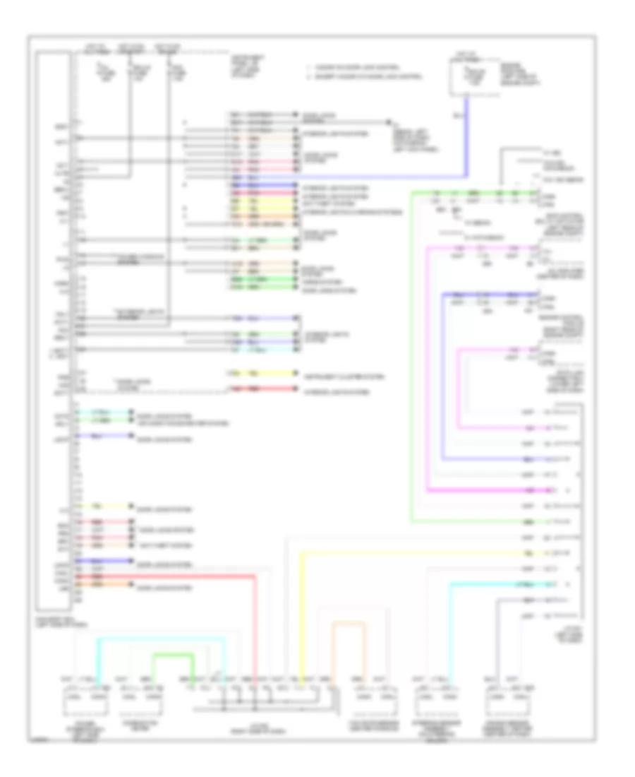
BODY CONTROL MODULES
Body Control Modules Wiring Diagram for Toyota Yaris 2011
List of elements for Body Control Modules Wiring Diagram for Toyota Yaris 2011:
- 3-door w/o door lock control
- A/c amplifier (center of dash)
- A20
- A21
- A24
- Acc
- Acc fuse 7.5a
- Act+
- Act-
- Actd
- Ad3
- Ad4
- Air bag sensor assembly center (center of dash)
- Air conditioning/heater system
- Altb
- Anti-theft system
- B28
- B30
- Bcty lgcy
- Becu
- C10
- Canh
- Canl
- Combination meter
- D/l fuse 25a
- D1 (sedan: left side of dash) (hatchback: left kick panel)
- D16
- D31
- Data link connector 3 (lower left side of dash)
- Dcty
- De1
- Door locks system
- E11
- E17
- Ecu-b fuse 7.5a
- Ecu-ig fuse 10a
- Engine control module (right rear of engine compt)
- Engine room r/b (left side of engine compt)
- Except 3-door w/o door lock control
- Exterior lights system
- Gnd1
- H15
- H16
- H17
- H18
- Haz
- Horn
- Horns system
- Hot at all times
- Hot in on or acc
- Hot in on or start
- Hrly
- Ile
- Instrument cluster system
- Instrument panel j/b (left side of dash)
- Interior lights & warning systems
- Interior lights system
- J/c d41 (left side of dash)
- J/c d42 (right side of dash)
- Ksw
- Lsr
- Lswd
- Lswp
- Main body ecu (left side of dash)
- Pcty
- Pkb
- Pnk
- Power steering ecu (left side of dash)
- Power windows system
- Prg
- Pws
- Rda
- Red
- Rrcy
- Skid control ecu w/ actuator (left rear of engine compt)
- Srx
- Steering sensor assembly (on steering column)
- Stx
- Trly
- Tx+
- Tx-
- Ul1
- Ul2
- Ul3
- W/ hatchback
- W/ sedan
- W/ vsc
- W/o vsc hatchback
- W/o vsc sedan
- Yaw rate sensor (center console)
COMPUTER DATA LINES
Computer Data Lines Wiring Diagram for Toyota Yaris 2011
List of elements for Computer Data Lines Wiring Diagram for Toyota Yaris 2011:
- (right side of dash) j/c d42
- A/c amplifier (center of dash)
- A21
- Ad2
- Ad3
- Ad4
- Airbag sensor assembly center (center of dash)
- B23
- Bat
- C1 (rear of engine)
- C11
- Ca1
- Canh
- Canl
- Combination meter
- D1 (sedan: left side of dash) (hatchback: left kick panel)
- D12
- D16
- D31
- D33
- D34
- D35
- Data link connector 3 (lower left side of dash)
- De1
- Dia
- E19
- E31
- Engine control module (right rear of engine compt)
- Hatchback
- Hot at all times
- Instrument panel j/b (left side of dash)
- J/c d34 & d35 (j/c d34 & j/c d35 sedan: center of dash) (j/c d35 hatchback: left side of dash)
- J/c d34 (center of dash)
- J/c d41 (left side of dash)
- J24
- Jd2
- Main body ecu (left side of dash)
- Obd 2 fuse 7.5a
- Occupant classification ecu (under front passenger's seat)
- Pnk
- Power steering ecu (left side of dash)
- Red
- Sedan
- Sedan w/ cruise control & hatchback
- Sedan w/o cruise control
- Sil
- Skid control ecu w/ actuator (left rear of engine compt)
- Steering sensor assembly (on steering column)
- Tac
- Tach
- Tire pressure warning ecu (right side of dash)
- Transponder key ecu (center of dash)
- Tx+
- Tx-
- W/ tire pressure warning system
- W/ vsc
- W/o tire pressure warning system
- W/o vsc hatch back
- W/o vsc sedan
- Yaw rate sensor (center console)
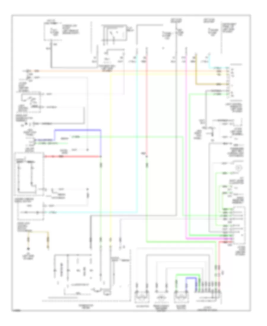
COOLING FAN
Cooling Fan Wiring Diagram for Toyota Yaris 2011
List of elements for Cooling Fan Wiring Diagram for Toyota Yaris 2011:
- (sedan: left side of engine compt) j/c a25
- A1 (left side of engine compt)
- A21
- Aa2
- B24
- C20
- Can h
- Can l
- Computer data lines system
- Cooling fan motor (sedan: center radiator support) (hatchback: center front of engine compt)
- Ecu-ig fuse 10a
- Engine control module (right rear of engine compt)
- Engine coolant temperature sensor (top rear of engine)
- Engine room j/b (left side of engine compt)
- Engine room r/b (left side of engine compt)
- Ethw
- Fan
- Fan relay 1
- Fan relay 2
- Fan2
- Hot at all times
- Hot in on or start
- Instrument panel j/b (left side of dash)
- Pnk
- Radiator fan resistor (left front of engine compt)
- Rdi fuse 30a
- Thw
CRUISE CONTROL
Cruise Control Wiring Diagram (1 of 2) for Toyota Yaris 2011
List of elements for Cruise Control Wiring Diagram (1 of 2) for Toyota Yaris 2011:
- (left side of dash) instrument panel j/b
- (left side of engine compt) a1
- +b2
- +bm
- +res
- -set
- A/t
- A1 (left side of engine compt)
- A21
- Aa2
- Accelerator position sensor (accelerator pedal assembly)
- Ad2
- Ad4
- B18
- B19
- B24
- B26
- B27
- Batt
- C1 (rear of engine)
- C20
- Ca1
- Cancel
- Canh
- Canl
- Ccs
- Computer data lines system
- Cruise control clutch switch (clutch pedal assembly)
- Cruise control switch
- Ecu-ig fuse 10a
- Efi fuse 20a
- Efi relay
- Engine control module (right rear of engine compt)
- Engine room j/b (left side of engine compt)
- Engine room r/b (left side of engine compt)
- Epa
- Epa2
- Eta
- Etcs fuse 10a
- Gauge fuse 10a
- Ge01
- Hot at all times
- Hot in on or start
- Ign fuse 7.5a
- Igsw
- Instrument panel j/b (left side of dash)
- J/c a25 (sedan: left side of engine compt)
- J/c d34 (center of dash)
- M/t
- Met fuse 7.5a
- Mrel
- Of dash)
- On/off
- Park/ neutral position switch (transaxle)
- Pnk
- Red
- Spd
- Spiral cable (hatchback: left side of dash) (sedan: center
- St1-
- Stop fuse 10a
- Stop lamp switch (brake pedal assembly)
- Stp
- Tach
- Throttle body assembly (hatchback: top rear of engine) (sedan: rear of engine)
- Vcp2
- Vcpa
- Vcta
- Vpa
- Vpa2
- Vta
- Vta1
- Vta2
Cruise Control Wiring Diagram (2 of 2) for Toyota Yaris 2011
List of elements for Cruise Control Wiring Diagram (2 of 2) for Toyota Yaris 2011:
- (left front hub assembly) left front speed sensor
- (left rear hub assembly) left rear speed sensor
- (right front hub assembly) right front speed sensor
- (right rear hub assembly) right rear speed sensor
- A1 (left side of engine compt)
- A15
- A2 (left side of engine compt)
- A30
- Aa1
- Aa2
- Ad3
- Aj1
- Ca2
- Can controller
- Can i/f
- Canh
- Canl
- Combination meter
- Computer data lines system
- Cpu
- Cruise ind
- D3 (left side of dash)
- Fl+
- Fl-
- Fr+
- Fr-
- Gnd1
- Hatch back w/o vsc
- I/f
- Ig+
- Ig1
- Led driver
- Pnk
- Red
- Rl+
- Rl-
- Rr+
- Rr-
- Sedan
- Sedan w/o vsc
- Set ind
- Skid control ecu w/ actuator (left rear of engine compt)
- Speed sensor (transaxle)
- W/ vsc
- Zj1
DEFOGGERS
Defoggers Wiring Diagram for Toyota Yaris 2011
List of elements for Defoggers Wiring Diagram for Toyota Yaris 2011:
- (hatchback)
- (left kick panel)
- (right kick panel)
- (sedan)
- A/c fuse 7.5a
- Air conditioning system
- De1
- Def fuse 30a (hatchback) 40a (sedan)
- Def relay
- Fd1
- Gauge fuse 10a
- Gd1
- Hatchback
- Heater
- Hot at all times
- Hot in on or start
- Id/up/mir htr fuse 10a
- Ig+
- Instrument panel j/b (left side of dash)
- Interior lights system
- J/b 5
- J/b 6
- J/b 6 (right kick panel)
- J/c d40 (left side of dash)
- J/c e10 (center of dash)
- J44
- Jd2
- Jd4
- Left outer rear view mirror
- M11
- Max hot switch
- Mj1
- Noise filter (rear window defogger) (3 door: base of "b" pillar) (5 door: rear of vehicle chassis)
- O1 (behind right taillight)
- Pnk
- Q12
- Rdef
- Rear window defogger
- Rear window defogger switch
- Right outer rear view mirror
- S10
- Sedan
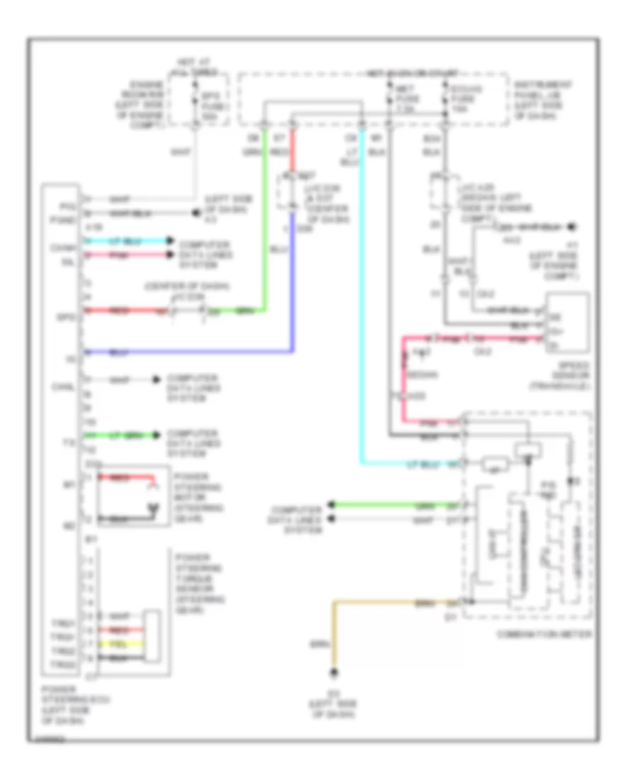
ELECTRONIC POWER STEERING
Electronic Power Steering Wiring Diagram for Toyota Yaris 2011
List of elements for Electronic Power Steering Wiring Diagram for Toyota Yaris 2011:
- (center of dash) j/c d36
- (left side of dash) a3
- A1 (left side of engine compt)
- A19
- Aa2
- Ad3
- B24
- Ca2
- Can controller
- Can i/f
- Canh
- Canl
- Combination meter
- Computer data lines system
- Cpu
- D3 (left side of dash)
- D31
- D36
- D37
- Ecu-ig fuse 10a
- Engine room r/b (left side of engine compt)
- Eps fuse 50a
- Hot at all times
- Hot in on or start
- I/f
- Ig+
- Instrument panel j/b (left side of dash)
- J/c a25 (sedan: left side of engine compt)
- J/c d36 & d37 (center of dash)
- Led driver
- Met fuse 7.5a
- P/s ind
- Pgnd
- Pig
- Pnk
- Power steering ecu (left side of dash)
- Power steering motor (steering gear)
- Power steering torque sensor (steering gear)
- Red
- Sedan
- Sil
- Spd
- Speed sensor (transaxle)
- Trq1
- Trq2
- Trqg
- Trqv
ENGINE PERFORMANCE
1.5L
1.5L, Engine Performance Wiring Diagram (1 of 4) for Toyota Yaris 2011
List of elements for 1.5L, Engine Performance Wiring Diagram (1 of 4) for Toyota Yaris 2011:
- (base of right "c" pillar) j1
- (fuel tank) fuel suction pump & gauge assembly
- (left side of engine compt) a1
- +b2
- +bm
- A1 (left side of engine compt)
- A21
- Aa1
- Aa2
- Acc cut relay (left side of dash)
- Accelerator position sensor (accelerator pedal assembly)
- Accr
- Ad3
- Ad4
- Aj1
- Anti-theft system
- B11
- B13
- B18
- B26
- B27
- B30
- Batt
- C/opn relay
- C2 (rear of engine)
- Ca2
- Canh
- Canister pressure sensor
- Canister pump module (left rear of vehicle)
- Canl
- Ccs
- Computer data lines system
- Cooling fans system
- Cruise control system
- Dome fuse 15a
- Ecu-b fuse 7.5a
- Efi 2 fuse 10a
- Efi fuse 20a
- Efi relay
- Els
- Els3
- Engine control module (right rear of engine compt)
- Engine room j/b (left side of engine compt)
- Engine room r/b (left side of engine compt)
- Epa
- Epa2
- Etcs fuse 10a
- Exterior lights system
- Fan
- Fan2
- Hatchback
- Hot at all times
- Hot in on or start
- Hot w/ def relay energized
- Id/up/ mir htr fuse 10a
- Ign fuse 7.5a
- Igsw
- Imi
- Imo
- Instrument panel j/b (left side of dash)
- Leak detection pump
- M11
- Mpmp
- Mrel
- Odms
- Pnk
- Power distribution system
- Pump
- Red
- S/d
- Sedan
- Spd
- Sta
- Starting/charging system
- Sti-
- Stop fuse 10a
- Stop lamp switch (brake pedal assembly)
- Stp
- Stsw
- Tach
- Vcp2
- Vcpa
- Vent valve
- Vpa
- Vpa2
- Vpmp
1.5L, Engine Performance Wiring Diagram (2 of 4) for Toyota Yaris 2011
List of elements for 1.5L, Engine Performance Wiring Diagram (2 of 4) for Toyota Yaris 2011:
- (rear of engine) c2
- (rear of engine) vsv (purge)
- (under center console) shift lock control ecu
- 5v ic
- Aa2
- Ad3
- Alt
- At3
- C1 (rear of engine)
- C20
- Ca1
- Can controller
- Can i/f
- Combination meter
- Computer data lines system
- Cpu
- D3 (left side of dash)
- D76
- E01
- E04
- Engine control module (right rear of engine compt)
- Eo2
- Hatchback
- Ht1b
- I/f
- Led driver
- Malfunction ind lamp
- Me01
- Nssd
- Pnk
- Prg
- Red
- Sedan
- Slu+
- Speedometer
- Star
- Starting/ charging system
- Tachometer
- Transmission control switch
1.5L, Engine Performance Wiring Diagram (3 of 4) for Toyota Yaris 2011
List of elements for 1.5L, Engine Performance Wiring Diagram (3 of 4) for Toyota Yaris 2011:
- (left side of engine compt) a1
- A/t
- A1 (left side of engine compt)
- Aa2
- Acc
- Ad2
- Ad3
- Ad4
- Ad5
- Am2
- Am2 fuse 15a
- B19
- B24
- Ca1
- Ca2
- Cruise control clutch switch (clutch pedal assembly)
- Ecu-ig fuse 10a
- Electronically controlled transmission solenoid (transaxle)
- Engine room j/b (left side of engine compt)
- Gauge fuse 10a
- Hot at all times
- Hot in on or start
- Ht1b
- Ig+
- Ig2
- Ig2 relay
- Ignition switch
- Instrument panel j/b (left side of dash)
- J/c a25 (left side of engine compt)
- Lock
- M/t
- Met fuse 7.5a
- Nca
- Off
- Ox1b
- Oxygen sensor (bank 1 sensor 2) (exhaust, after catalytic converter)
- Park/ neutral position switch (transaxle)
- Pnk
- Red
- Sedan
- Sl/
- Slt+
- Slt-
- Slu+
- Slu-
- Speed sensor (transaxle)
- Start
- Tho
- Throttle body assembly (rear of engine)
- Vta
- Vta2
1.5L, Engine Performance Wiring Diagram (4 of 4) for Toyota Yaris 2011
List of elements for 1.5L, Engine Performance Wiring Diagram (4 of 4) for Toyota Yaris 2011:
- (rear of engine) c1
- (rear of engine) c2
- (top of intake manifold) fuel injectors
- (top of valve cover)
- A1a+
- A1a-
- Air fuel ratio sensor (bank 1 sensor 1) (hatchback: right side of engine, in exhaust pipe) (sedan: left front of engine compt)
- C1 (rear of engine)
- C20
- Camshaft position sensor (rear of engine)
- Camshaft timing oil control valve (front of cylinder head)
- Cp1
- Crankshaft position sensor (front of engine)
- E03
- E2g
- Eknk
- Engine control module (right rear of engine compt)
- Engine coolant temperature sensor (top rear of engine)
- Eppm
- Eta
- Etha
- Etho
- Ethw
- Ex1b
- G2+
- Ge01
- Gnd
- Ha1a
- Igf
- Igf1
- Ignition coil 1
- Ignition coil 2
- Ignition coil 3
- Ignition coil 4
- Igt
- Igt1
- Igt2
- Igt3
- Igt4
- Knk1
- Knock control sensor (bank 1) (left side of engine)
- Mass air flow meter (air intake assembly)
- Nca
- Ne+
- Ne-
- Noise filter (3 door: base of "b" pillar) (5 door: rear of vehicle chassis)
- Nt+
- Nt-
- Oc1+
- Oc1-
- Ox1b
- Pnk
- Ppmp
- Red
- Slt+
- Slt-
- Slu-
- Speed sensor (turbine) (transaxle)
- Tha
- Tho1
- Thw
- Vcpp
- Vcta
- Vta1
- Vta2
EXTERIOR LIGHTS
Backup Lamps Wiring Diagram for Toyota Yaris 2011
List of elements for Backup Lamps Wiring Diagram for Toyota Yaris 2011:
- A/t
- A30
- B19
- B22
- Backup lamp switch (transaxle)
- Ca1
- Gauge fuse 10a
- Hot in on or start
- Instrument panel j/b (left side of dash)
- J/c j28 & j29 (base of left "c" pillar)
- J1 (base of right "c" pillar)
- J2 (base of left "c" pillar)
- J28
- J29
- Left rear combination light backup
- M/t
- Park/ neutral position switch (transaxle)
- Red
- Right rear combination light backup
Exterior Lamps Wiring Diagram (1 of 2) for Toyota Yaris 2011
List of elements for Exterior Lamps Wiring Diagram (1 of 2) for Toyota Yaris 2011:
- A1 (left side of engine compt)
- A10
- A24
- A28
- A29
- Alt fuse 120a
- B1 (left side of engine compt)
- B13
- B33
- Fusible link block (left rear of engine compt)
- Hatchback
- Hot at all times
- Instrument panel j/b (left side of dash)
- J/c a24 & b13 (left side of engine compt)
- Left front side marker lamp
- Left front side turn signal lamp (hatchback)
- Left front turn signal lamp
- Left parking lamp
- Left turn signal, side marker & parking lamp
- Main body ecu (left side of dash)
- Panel 1 fuse 7.5a
- Parking
- Pnk
- Right front side marker lamp
- Right front side turn signal lamp (hatchback)
- Right front turn signal lamp
- Right parking lamp
- Right turn signal, side marker & parking lamp
- Sedan
- Side marker
- T-lp relay
- Tail fuse 10a
- Trly
- Turn
Exterior Lamps Wiring Diagram (2 of 2) for Toyota Yaris 2011
List of elements for Exterior Lamps Wiring Diagram (2 of 2) for Toyota Yaris 2011:
- (base of left "c" pillar) j/c j28 & j29
- (hatchback w/o vsc)
- (sedan bulb type) center stop lamp
- (sedan w/o vsc)
- (w/ vsc)
- A12
- A27
- A28
- B12
- B14
- B18
- B21
- B31
- B32
- Center stop lamp
- Combination meter
- Cruise control system
- D1 (hatchback: left kick panel) (sedan: left side of dash)
- D2 (right kick panel)
- D3 (left side of dash)
- D76
- D77
- E17
- E28
- Engine controls system
- Engine room r/b (left side of engine compt)
- Flash relay
- Gauge fuse 10a
- Hatchback
- Haz
- Haz fuse 10a
- Hazard warning signal switch
- Head
- Headlamp dimmer switch assembly
- Hot at all times
- Hot in on or start
- Instrument panel j/b (left side of dash)
- J/b 6 (right kick panel)
- J1 (base of right "c" pillar)
- J2 (base of left "c" pillar)
- J28
- J29
- J34
- Left license plate lamp
- Left rear combin- ation lamp
- Left turn ind
- License plate lamp
- Light control switch
- Lj1
- Mj1
- Off
- Pnk
- Red
- Right license plate lamp
- Right rear combination lamp
- Right turn ind
- S11
- S12
- S13
- S16
- S17
- S18
- Sedan
- Sedan bulb type
- Sedan led type
- Shift lock control ecu (hatchback: under center console) (sedan: under center floor console)
- Skid control ecu w/actuator (left rear of engine compt)
- Stop
- Stop fuse 10a
- Stop lamp switch (brake pedal assembly)
- Stp
- Tail
- Tail ind (canada)
- Turn
- Turn signal switch
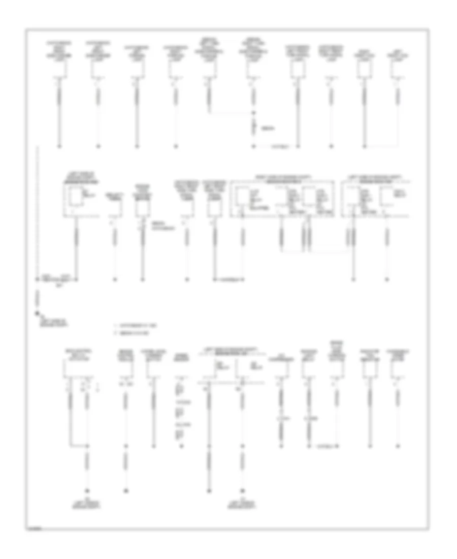
GROUND DISTRIBUTION
Ground Distribution Wiring Diagram (1 of 3) for Toyota Yaris 2011
List of elements for Ground Distribution Wiring Diagram (1 of 3) for Toyota Yaris 2011:
- (hatchback) back door courtesy switch
- (hatchback) back door position switch
- (hatchback) center stop lamp
- (hatchback) license plate lamp
- (sedan bulb) center stop lamp
- (sedan led) center stop lamp
- (sedan) left license plate lamp
- (sedan) luggage door lock assembly
- (sedan) right license plate lamp
- A19
- A3 (left side of dash)
- Aa1
- Ad2
- Air fuel ratio sensor (bank 1 sensor 1) shield
- Aj1
- C1 (rear of engine)
- C2 (rear of engine)
- C20
- Ca1
- Ca2
- Camshaft position sensor shield
- Canister pump module
- Combination meter
- Crankshaft position sensor shield
- D10
- D3 (left side of dash)
- Data link connector 3
- Door control receiver
- Engine control module
- Fuel suction pump & gauge assembly
- Hatchback
- Ignition coil 1
- Ignition coil 2
- Ignition coil 3
- Ignition coil 4
- J1 (base of right "c" pillar)
- J2 (base of left "c" pillar)
- J34
- J35
- J40
- J41
- J42
- J43
- Joint connector d34 (center of dash)
- Knock control sensor shield (bank 1)
- Left rear combination lamp
- Lj1
- Mj1
- Mn1
- N1 (hatchback) (center of rear door)
- Nca
- O1 (behind right taillight)
- Oxygen sensor (bank 1 sensor 2) shield
- Power steering ecu
- Radio receiver assembly
- Rear window defogger
- Right rear combination lamp
- Sedan
- Spiral cable
- Tire pressure warning ecu
- W/ cruise
- W/ cruise control
- W/o cruise
Ground Distribution Wiring Diagram (2 of 3) for Toyota Yaris 2011
List of elements for Ground Distribution Wiring Diagram (2 of 3) for Toyota Yaris 2011:
- (hatchback) left front side marker lamp
- (hatchback) left front side turn signal lamp
- (hatchback) left front turn signal lamp
- (hatchback) left parking lamp
- (hatchback) right front side marker lamp
- (hatchback) right front side turn signal lamp
- (hatchback) right front turn signal lamp
- (hatchback) right parking lamp
- (left side of engine compt) engine room j/b
- (left side of engine compt) engine room r/b
- (right side of engine compt) engine room r/b 2
- (sedan) left turn signal, side marker & parking lamp
- (sedan) right turn signal, side marker & parking lamp
- A/c compressor
- A1 (left side of engine compt)
- A2 (left side of engine compt)
- A21
- Aa2
- Ad5
- B1 (left side of engine compt)
- B41
- Brake fluid level warning switch
- Ca1
- Ca2
- Efi relay
- Engine control module
- Engine hood courtesy switch
- Fan 2 relay
- H-lp/ amt relay (if equipped)
- Hatchback
- Hatchback w/ vsc
- Htr sub 1 relay (w/ ptc heater)
- Htr sub 2 relay (w/ ptc heater)
- Htr sub 3 relay (w/ ptc heater)
- Ig2 relay
- Left front fog lamp
- Radiator fan resistor
- Right front fog lamp
- Running light relay
- Security horn
- Sedan
- Sedan w/o vsc
- Skid control ecu w/ actuator
- Speed sensor
- St relay
- Water level warning switch
- Windshield wiper motor
Ground Distribution Wiring Diagram (3 of 3) for Toyota Yaris 2011
List of elements for Ground Distribution Wiring Diagram (3 of 3) for Toyota Yaris 2011:
- (hatchback)
- (hatchback) cigarette lighter or power outlet
- (hatchback) door lock control switch
- (hatchback) passenger seat belt warning lamp
- (sedan)
- (sedan) cigarette lighter or power outlet
- (sedan) front passenger's side door lock control switch
- A/c amplifier
- A15
- Air bag sensor assembly center
- Blower resistor
- Blower switch
- Center room lamp
- D1 (hatchback: left kick panel) (sedan: left side of dash)
- D16
- D2 (right kick panel)
- D77
- Data link connector 3
- De1
- Driver's side door lock assembly
- Driver's side door lock control switch
- E12
- E14
- E28
- E30
- Ed1
- Flash relay
- Front passenger's side door lock assembly
- Hatchback
- Hatchback w/ vsc
- Hazard warning signal switch
- Headlamp dimmer switch assembly
- Hj1
- Htr relay
- Ig 1 relay
- Ij1
- Instrument panel j/b (left side of dash)
- J/b 5 (left kick panel)
- J/b 6 (right kick panel)
- Junction connector d40 (left side of dash)
- Junction connector e10 (center of dash)
- Key interlock solenoid
- Left outer rear view mirror
- Left rear door lock assembly
- Light control rheostat
- Main body ecu
- Map lamp
- Noise filter
- Occupant classi- fication ecu
- Outer mirror switch
- Power window master switch
- Pwr relay
- Rear window defogger switch
- Right outer rear view mirror
- Right rear door lock assembly
- Security indicator lamp
- Sedan
- Sedan w/ vsc
- Shift lock control ecu
- Steering sensor assembly
- Theft warning ecu
- Transponder key ecu
- Unlock warning switch
- Vsc off switch
- W/ rear power window
- W/o power window
- W/o rear power window
- Windshield wiper switch assembly
- Yaw rate sensor
HEADLIGHTS
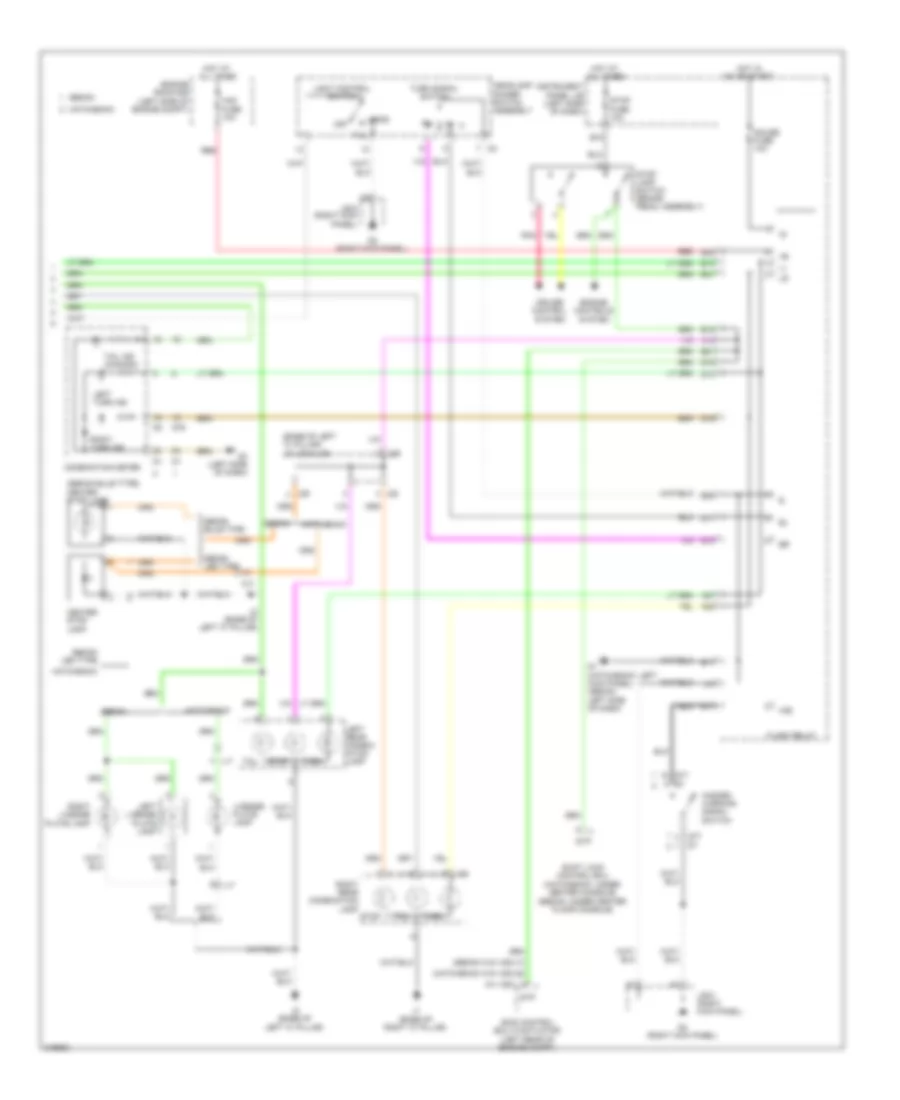
Headlights Wiring Diagram, with DRL for Toyota Yaris 2011
List of elements for Headlights Wiring Diagram, with DRL for Toyota Yaris 2011:
- (left side of engine compt) a1
- (left side of engine compt) j/c a24 & b13
- (right side of engine compt) engine room r/b 2
- A1 (left side of engine compt)
- A24
- Aa2
- Ad2
- Ad3
- Ad5
- B1 (left side of engine compt)
- B13
- B16
- B17
- B30
- B34
- B35
- Ba1
- Beam ind
- Bfg
- C16
- Ca1
- Chg-
- Combination meter
- D1 (hatchback: left kick panel) (sedan: left side of dash)
- D3 (left side of dash)
- D36
- D37
- D76
- Dimmer switch
- Drl
- E12
- E17
- Ecu-b fuse 7.5a
- Ecu-ig fuse 10a
- Engine room r/b (left side of engine compt)
- Flash
- Fog
- Fog light switch
- Fr fog fuse 15a
- Front fog ind
- Front fog light relay (left side of dash)
- Generator (left front of engine)
- H-lp lh/ h-lp lo lh fuse 10a
- H-lp rh/ h-lp lo rh fuse 10a
- H-lp/amt relay
- H12
- Hatchback
- Head
- Head ind (usa)
- Headlamp dimmer switch assembly
- High
- Hot at all times
- Hot in on or start
- Instrument panel j/b (left side of dash)
- J/c d36 & d37 (center of dash)
- J/c d37 (center of dash)
- J/c d39 (center of dash)
- J/c d40 (left side of dash)
- Left front fog lamp
- Left headlamp
- Lfg
- Light control switch
- Low
- Off
- Parking brake switch (parking brake assembly)
- Pkb
- Pnk
- Red
- Right front fog lamp
- Right headlamp
- Running light relay (center of dash)
- Sedan
- Tail
- W/ h-lp/ amt relay
- W/o h-lp/ amt relay
Headlights Wiring Diagram, without DRL for Toyota Yaris 2011
List of elements for Headlights Wiring Diagram, without DRL for Toyota Yaris 2011:
- (left side of dash) d3
- (left side of dash) j/c d40
- (left side of engine compt) j/c a24 & b13
- (right side of engine compt) engine room r/b 2
- A1 (left side of engine compt)
- A24
- Aa2
- Ad2
- Ad3
- B1 (left side of engine compt)
- B13
- B16
- B17
- B30
- B34
- B35
- Ba1
- Beam ind
- Bfg
- C16
- Combination meter
- D1 (hatchback: left kick panel) (sedan: left side of dash)
- D76
- Dimmer switch
- E12
- E17
- Ecu-b fuse 7.5a
- Engine room r/b (left side of engine compt)
- Flash
- Fog light switch
- Fr fog fuse 15a
- Front fog ind
- Front fog light relay (left side of dash)
- H-lp lh/ h-lp lo lh fuse 10a
- H-lp rh/ h-lp lo rh fuse 10a
- H-lp/amt relay
- Hatchback
- Head
- Head ind (usa)
- Headlamp dimmer switch assembly
- High
- Hot at all times
- Instrument panel j/b (left side of dash)
- J/c d37 (center of dash)
- Left front fog lamp
- Left headlamp
- Lfg
- Light control switch
- Low
- Off
- Pnk
- Red
- Right front fog lamp
- Right headlamp
- Sedan
- Tail
- W/ h-lp/amt relay
- W/o h-lp/amt relay
HORN
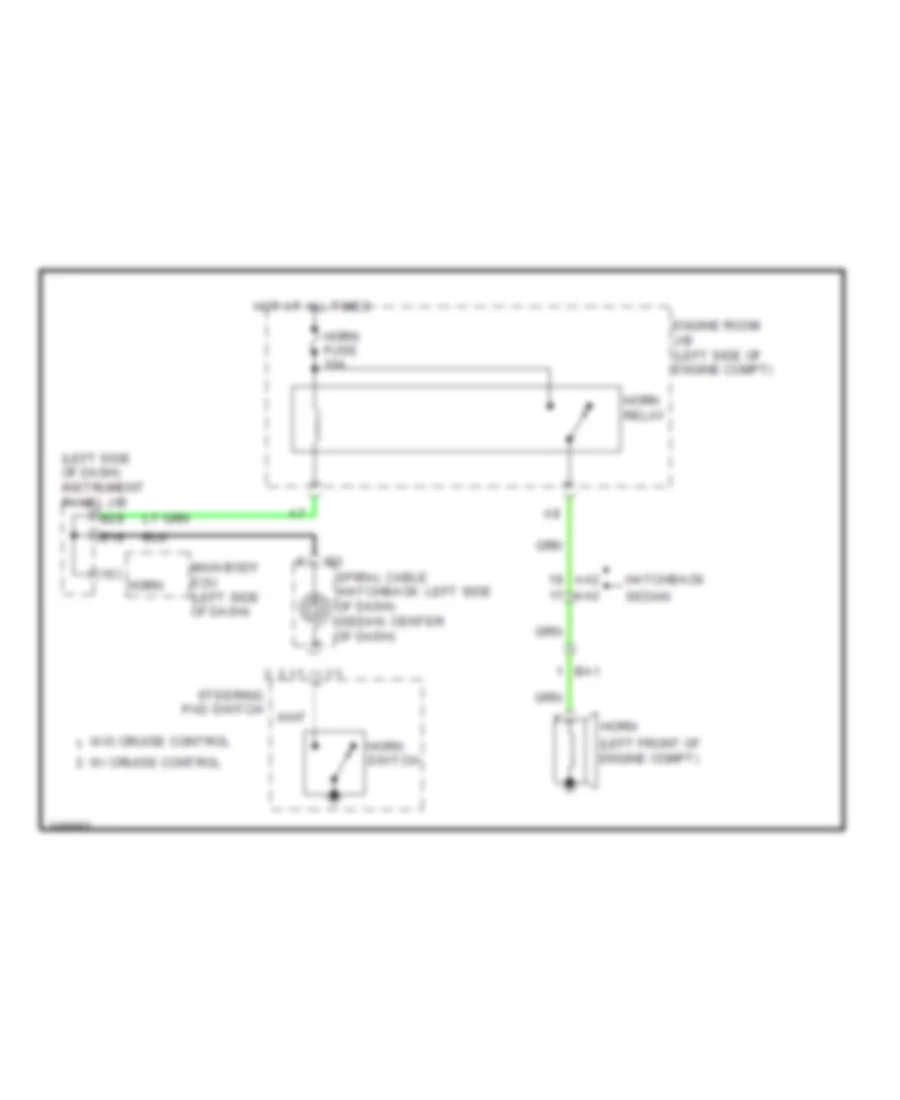
Horn Wiring Diagram for Toyota Yaris 2011
List of elements for Horn Wiring Diagram for Toyota Yaris 2011:
- (left front of engine compt)
- (left side of dash) instrument panel j/b
- Aa2
- B28
- Ba1
- E18
- Engine room j/b (left side of engine compt)
- Hatchback
- Horn
- Horn fuse 10a
- Horn relay
- Horn switch
- Hot at all times
- Main body ecu (left side of dash)
- Sedan
- Spiral cable (hatchback: left side of dash) (sedan: center of dash)
- Steering pad switch
- W/ cruise control
- W/o cruise control
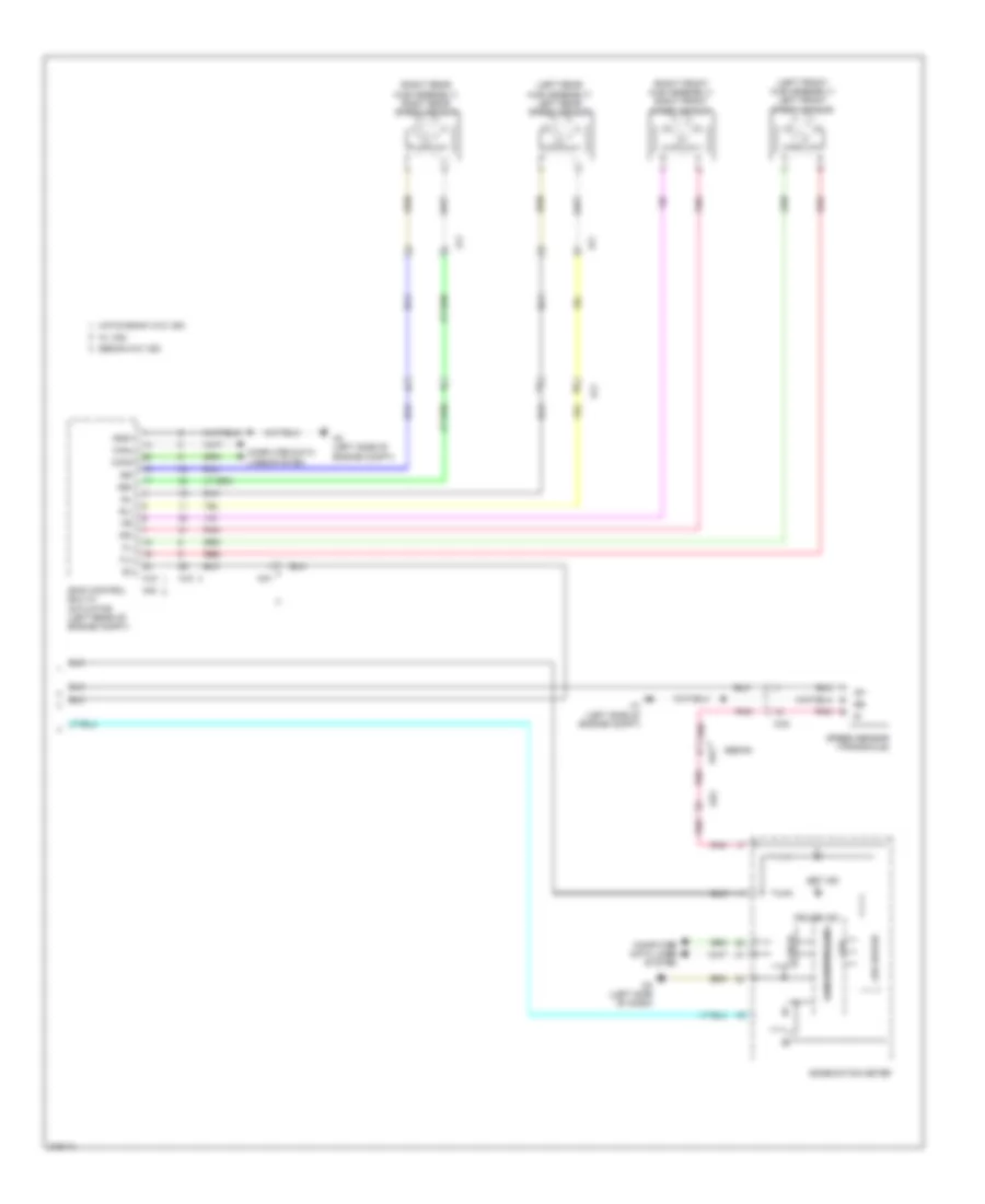
INSTRUMENT CLUSTER
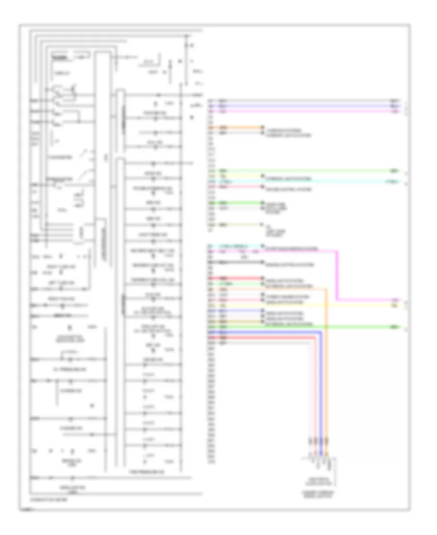
Instrument Cluster Wiring Diagram, Hatchback (1 of 2) for Toyota Yaris 2011
List of elements for Instrument Cluster Wiring Diagram, Hatchback (1 of 2) for Toyota Yaris 2011:
- (canada)
- 5v ic
- A1 (left side of engine compt)
- A10
- A11
- A12
- A13
- A14
- A15
- A16
- A17
- A18
- A19
- A20
- A21
- A22
- A23
- A24
- Abs ind
- Ad3
- B10
- B11
- B12
- B13
- B14
- B15
- B16
- Beam ind
- Brake fluid level warning switch (brake fluid reservoir)
- Brake ind
- Buzzer
- Can controller
- Can i/f
- Charge ind
- Clock sw drive monitor
- Combination meter
- Computer data lines system
- Cpu
- Cruise control system
- Cruise ind
- D3 (left side of dash)
- Dial ind
- Display
- Door ind
- Driver's seat belt ind
- Engine controls system
- Exterior lights system
- Front fog ind
- Headlamp ind (usa)
- Headlights system
- I/f
- Illumination i/f
- Interior lights system
- Led driver
- Left turn ind
- Maint reqd ind
- Malfunction indicator lamp
- Oil pressure ind
- P/s ind
- Pnk
- Pointer ind
- Red
- Right turn ind
- Set ind
- Slip ind
- Slip off ind (w/ vsc off switch)
- Speedometer
- Srs ind
- Starting/charging system
- Tachometer
- Tail ind
- Temperature cool ind
- Temperature hot ind
- Tire pressure ind
- Trac off ind (w/ vsc off switch)
- Trip switch
- Warning systems
- Washer ind
- Wiper/washer system
Instrument Cluster Wiring Diagram, Hatchback (2 of 2) for Toyota Yaris 2011
List of elements for Instrument Cluster Wiring Diagram, Hatchback (2 of 2) for Toyota Yaris 2011:
- A13
- A20
- A21
- A24
- Aa2
- Ad3
- B26
- B30
- Back door courtesy switch (base of back door)
- Bcty
- Ca1
- Canh
- Canl
- Computer data lines system
- D31
- D33
- D36
- D37
- Dcty
- Ecu-b fuse 7.5a
- Engine control module (right rear of engine compt)
- Engine oil pressure switch (left front of engine compt)
- Engine room r/b (left side of engine compt)
- Fuel suction pump & gage assembly (fuel tank)
- Gage
- Hot at all times
- Hot in on or start
- Instrument panel j/b (left side of dash)
- J/c d36 & d37 (center of dash)
- J/c j29 (base of left "c" pillar)
- J1 (base of right "c" pillar)
- Left front door courtesy switch (left front door)
- Left rear door courtesy switch (base of "c" pillar)
- Main body ecu (left side of dash)
- Met fuse 7.5a
- Mj1
- Mn1
- N1 (center of rear door)
- Panel 1 fuse 7.5a
- Parking brake switch (parking brake assembly)
- Pcty
- Pkb
- Power steering ecu (left side of dash)
- Red
- Right front door courtesy switch (lower right "b" pillar)
- Right rear door courtesy switch (base of "c" pillar)
- Rrcy
- Spd
- Tire pressure warning ecu (right side of dash)
Instrument Cluster Wiring Diagram, Sedan (1 of 2) for Toyota Yaris 2011
List of elements for Instrument Cluster Wiring Diagram, Sedan (1 of 2) for Toyota Yaris 2011:
- (a/t)
- 5v ic
- A10
- A11
- A12
- A13
- A14
- A15
- A16
- A17
- A18
- A19
- A20
- A21
- A22
- A23
- A24
- Abs ind
- Ad3
- B10
- B11
- B12
- B13
- B14
- B15
- B16
- B17
- B18
- B19
- B20
- B21
- B22
- B23
- B24
- B25
- B26
- B27
- B28
- B29
- B30
- B31
- B32
- B33
- B34
- B35
- B36
- B37
- B38
- B39
- B40
- Beam ind
- Brake ind (usa)
- Buzzer
- Can controller
- Can i/f
- Charge ind
- Combination meter
- Computer data lines system
- Cpu
- Cruise control system
- Cruise ind
- D (a/t)
- D3 (left side of dash)
- D76
- Dial ind
- Display
- Door ind
- Driver's seat belt ind
- Engine controls system
- Exterior lights system
- Front fog ind
- Hazard warning signal switch
- Headlamp ind (usa)
- Headlights system
- I/f
- Illumination i/f
- Interior lights system
- L (a/t)
- Led driver
- Left turn ind
- Maint reqd ind
- Malfunction indicator lamp
- N (a/t)
- Odo/trip & clock switch
- Oil pressure ind
- P (a/t)
- Pbew
- Pnk
- Pointer ind
- Power steering ind
- R (a/t)
- Red
- Right turn ind
- Set ind
- Slip ind
- Slip off ind (w/ vsc off switch)
- Speedometer
- Srs ind
- Starting/charging system
- Tachometer
- Temperature cool ind
- Temperature hot ind
- Tire pressure ind
- Trac off ind (w/ vsc off switch)
- Tx+1
- Warning systems
- Washer ind
- Wiper/washer system
Instrument Cluster Wiring Diagram, Sedan (2 of 2) for Toyota Yaris 2011
List of elements for Instrument Cluster Wiring Diagram, Sedan (2 of 2) for Toyota Yaris 2011:
- A1 (left side of engine compt)
- A13
- A20
- A21
- A24
- Aa2
- Ad3
- B26
- B30
- Brake fluid level warning switch (brake fluid reservoir)
- Ca1
- Canh
- Canl
- Computer data lines system
- D31
- D33
- D36
- D37
- D74
- Dcty
- Ecu-b fuse 7.5a
- Engine control module (right rear of engine compt)
- Engine oil pressure switch (left front of engine compt)
- Engine room r/b (left side of engine compt)
- Fuel suction pump & gage assembly (fuel tank)
- Gage
- Hot at all times
- Hot in on or start
- Instrument panel j/b (left side of dash)
- J/c d36 & d37 (center of dash)
- J1 (base of right "c" pillar)
- Left front door courtesy switch (left front door)
- Left rear door courtesy switch (base of "c" pillar)
- Main body ecu (left side of dash)
- Met fuse 7.5a
- Panel 1 fuse 7.5a
- Parking brake switch (parking brake assembly)
- Pcty
- Pkb
- Power steering ecu (left side of dash)
- Radio receiver assembly
- Red
- Right front door courtesy switch (lower right "b" pillar)
- Right rear door courtesy switch (base of "c" pillar)
- Rrcy
- Spd
- Tire pressure warning ecu (right side of dash)
INTERIOR LIGHTS
Courtesy Lamps Wiring Diagram for Toyota Yaris 2011
List of elements for Courtesy Lamps Wiring Diagram for Toyota Yaris 2011:
- 3 door w/o door lock control
- 5v ic
- A20
- A21
- A24
- Aa2
- Acc
- Acc fuse 7.5a
- Altb
- B13
- B30
- Back door courtesy switch (base of back door)
- Bcty
- Becu
- Can controller
- Can i/f
- Canh
- Canl
- Center room lamp
- Combination meter
- Computer data lines system
- Cpu
- D/l fuse 25a
- D1 (hatchback: left kick panel) (sedan: left side of dash)
- D3 (left side of dash)
- D39
- Dcty
- Dome fuse 15a
- Door
- E17
- Ecu-b fuse 7.5a
- Engine room r/b (left side of engine compt)
- Except 3 door & w/ door lock control
- Gnd1
- H/b
- Hatchback
- Hot at all times
- Hot in acc or on
- Hot in on or start
- Ile
- Instrument panel j/b (left side of dash)
- J/b 5 (left kick panel)
- J/c d38 & d39 (center d38 of dash)
- J/c j28 & j29 (base of left "c" pillar)
- J2 (base of left "c" pillar)
- J28
- J29
- Jd1
- Ksw
- Led driver
- Left front door courtesy switch (left front door)
- Left rear door courtesy switch (base of "c" pillar)
- Lgcy
- Luggage door lock assembly (base of rear door)
- Luggage room lamp
- Main body ecu (left side of dash)
- Map lamp
- Met fuse 7.5a
- Mj1
- Mn1
- N1 (center of rear door)
- Off
- Pcty
- Pnk
- Red
- Right front door courtesy switch (lower right "b" pillar)
- Right rear door courtesy switch (base of "c" pillar)
- Room lamp diode (base of left "c" pillar)
- Rrcy
- S/d
- Sedan
- Unlock warning switch (left side of dash)
Instrument Illumination Wiring Diagram for Toyota Yaris 2011
List of elements for Instrument Illumination Wiring Diagram for Toyota Yaris 2011:
- A/c switch
- A/t shift lever illumination
- A28
- Alt fuse 120a
- Blower switch
- Combination meter
- Cpu
- D10
- D11
- D3 (left side of dash)
- D36
- D37
- D38
- D39
- De1
- Dial ind
- Dim
- Door lock control switch (hatchback)
- Fusible link block (left rear of engine compt)
- Gauge fuse 10a
- Hatch- back
- Hatchback
- Hazard warning signal switch
- Head
- Headlamp dimmer switch assembly
- Hot at all times
- Hot in on or start
- I/f
- Ill+
- Ill-
- Illumination i/f
- Instrument panel j/b (left side of dash)
- J/b 6 (right kick panel)
- J/c d36 & d37 (center of dash)
- J/c d38 & d39 (center of dash)
- J/c d40 (left side of dash)
- J/c e10 (center of dash)
- Light control rheostat (left side of dash)
- Light control switch
- Main body ecu (left side of dash)
- Met fuse 7.5a
- Off
- P10
- Panel 1 fuse 7.5a
- Passenger seat belt warning lamp (hatchback)
- Pointer ind
- Radio receiver assembly
- Rear window defogger switch
- Red
- Sedan
- T-lp relay
- Tail
- Trly
- Vsc off switch
POWER DISTRIBUTION
Power Distribution Wiring Diagram (1 of 3) for Toyota Yaris 2011
List of elements for Power Distribution Wiring Diagram (1 of 3) for Toyota Yaris 2011:
- A21
- A27
- A28
- Abs1/
- Abs2/
- Acc
- Acc cut relay (left side of dash)
- Acc fuse 7.5a
- Acc2 fuse 7.5a
- Accr
- Ad4
- Air conditioning system
- Alt fuse 120a
- Alt-s fuse 7.5a
- Anti-lock brakes system
- Anti-theft system
- B13
- B27
- Battery
- C/opn relay
- Cig fuse 15a
- Cigarette lighter or power outlet
- Cooling fans system
- D14
- Dome fuse 15a
- E16
- E21
- Ecu-b fuse 7.5a
- Electronic power steering system
- Engine control module (right rear of engine compt)
- Engine controls & cruise control systems
- Engine controls system
- Engine room j/b (left side of engine compt)
- Engine room r/b (left side of engine compt)
- Eps fuse 50a
- Etcs fuse 10a
- Exterior lights system
- Fuse block (hatchback: left side of dash)
- Fusible link block (left rear of engine compt)
- Generator
- H-lp lh/ h-lp lo lh fuse 10a
- H-lp rh/ h-lp lo rh fuse 10a
- Hatchback
- Haz fuse 10a
- Headlights & anti-theft systems
- Headlights system
- Htr fuse 40a
- Htr sub1 fuse 30a
- Htr sub2 fuse 40a
- Ign fuse 7.5a
- Instrument panel j/b (left side of dash)
- Interior lights & door locks systems
- J/b 6 (hatchback: right kick panel)
- J/c d40 (left side of dash)
- Main body ecu
- Main fuse 60a
- Met fuse 7.5a
- Mirrors system
- Pnk
- Rdi fuse 30a
- Red
- Sedan
- Shift interlock system
- Sound systems
- St fuse 30a
- Starting/ charging system
- To engine room j/b (diagram 2 of 3)
- To ig2 relay (diagram 2 of 3)
- To ignition switch (diagram 2 of 3)
- To t-lp relay (diagram 3 of 3)
- Vsc1 fuse 50a
- Vsc2 fuse 30a
Power Distribution Wiring Diagram (2 of 3) for Toyota Yaris 2011
List of elements for Power Distribution Wiring Diagram (2 of 3) for Toyota Yaris 2011:
- A/c fuse 7.5a
- A1 (left side of engine compt)
- A25
- Aa2
- Acc
- Ad2
- Ad4
- Air conditioning & defogger systems
- Am1
- Am2
- Am2 fuse 15a
- Anti-lock brakes, anti-theft, electronic power steering & headlights systems
- B19
- B24
- B36
- D1 (hatchback: left kick panel) (sedan: left side of dash)
- Def relay
- E17
- Ecu-ig fuse 10a
- Efi fuse 20a
- Efi relay
- Electronic power steering, sound cruise control, cooling fans, anti-lock brakes, & engine control systems
- Engine controls system
- Engine room j/b (left side of engine compt)
- Exterior lights, starting/charging, cruise control & transmissions systems
- Flash relay
- From acc cut relay (diagram 1 of 3)
- From engine room j/b (diagram 1 of 3)
- From ig2 relay (diagram 2 of 3)
- From ign fuse (diagram 1 of 3)
- Gauge fuse 10a
- Horn fuse 10a
- Horn relay
- Htr relay
- Ig1
- Ig1 relay
- Ig2
- Ig2 relay
- Ignition switch
- Instrument panel j/b (left side of dash)
- Interior lights system
- J/b 6 (hatchback: right kick panel)
- Lock
- Main body ecu
- Off
- On off
- Pnk
- Red
- Rr wip fuse 15a
- S10
- S15
- Shift interlock system
- St2
- Start
- Starting/ charging system
- To am1 fuse (diagram 3 of 3)
- To ignition switch (diagram 2 of 3)
- To pwr relay (diagram 3 of 3)
- Wip fuse 25a
- Wiper/ washer system
- Wiper/washer system
- Wsh fuse 15a
Power Distribution Wiring Diagram (3 of 3) for Toyota Yaris 2011
List of elements for Power Distribution Wiring Diagram (3 of 3) for Toyota Yaris 2011:
- (diagram 3 of 3)
- A10
- A29
- Am1 fuse 25a
- B15
- B18
- B33
- Computer data lines system
- Cruise control, anti-lock brakes, transmissions, engine controls, shift interlock & exterior lights systems
- D/l fuse 25a
- Def fuse (sedan) 40a (hatch back) 30a
- Def relay
- Engine control system
- Exterior lights & instrument cluster systems
- Exterior lights system
- Fr fog fuse 15a
- From alt fuse (diagram 1 of 3)
- From d/l fuse j
- From ig1 relay (diagram 2 of 3)
- From ig1 relay f (diagram 2 of 3)
- From ignition switch (diagram 2 of 3)
- Headlights system
- Instrument panel j/b (left side of dash)
- Main body ecu
- Noise filter
- Obd2 fuse 7.5a
- P10
- Panel 1 fuse 7.5a
- Pnk
- Pwr relay
- Red
- Stop fuse 10a
- T-lp relay
- Tail fuse 10a
- To obd2 fuse (diagram 3 0f 3)
POWER DOOR LOCKS
Power Door Locks Wiring Diagram, with Keyless Entry for Toyota Yaris 2011
List of elements for Power Door Locks Wiring Diagram, with Keyless Entry for Toyota Yaris 2011:
- (center of dash) j/c d38 & d39
- (left kick panel) j/b 5
- (left side of dash) unlock warning switch
- A20
- A21
- A24
- Aa2
- Acc
- Acc fuse 7.5a
- Act+
- Act-
- Actd
- Altb
- Anti-theft system
- B13
- B30
- Back
- Back door courtesy switch (hatchback) (base of back door)
- Back door lock assembly (hatchback) (base of back door)
- Becu
- Center room lamp
- D/l fuse 25a
- D1 (hatchback: left kick panel) (sedan: left side of dash)
- D38
- D39
- Dcty
- Dome fuse 15a
- Door
- Door control receiver (base of left "d" pillar)
- Driver's side door lock assembly (driver's door)
- E17
- Ecu-b fuse 7.5a
- Ecu-ig fuse 10a
- Engine room r/b (left side of engine compt)
- Fd1
- Flash relay
- Front passenger's side door lock assembly (front passenger's door)
- Gd1
- Gnd
- Gnd1
- H17
- H18
- Hatch-
- Hatchback
- Haz
- Hj1
- Hot at all times
- Hot in on or acc
- Hot in on or start
- Ij1
- Ile
- Instrument panel j/b (left side of dash)
- J/b 5 (left kick panel)
- J/b 6 (right kick panel)
- J/c j29 & j28 (base of left "c" pillar)
- J/c j29 (base of left "c" pillar)
- J2 (base of left "c" pillar)
- J28
- J29
- Jd1
- Jd2
- Ksw
- Left front door courtesy switch (left front door)
- Left rear door courtesy switch (base of "c" pillar)
- Left rear door lock assembly (left rear door)
- Lgcy
- Lock
- Lsr
- Lssr
- Lswd
- Lswp
- Main body ecu
- Mj1
- Mn1
- N1 (center of rear door)
- Off
- Pcty
- Pnk
- Prg
- Rda
- Red
- Right front door courtesy switch (lower right "b" pillar)
- Right rear door courtesy switch (base of "c" pillar)
- Right rear door lock assembly (right rear door)
- Rrcy
- Sedan
- Srx
- Stx
- Unlock
- Unlock detection
Power Door Locks Wiring Diagram, without Keyless Entry for Toyota Yaris 2011
List of elements for Power Door Locks Wiring Diagram, without Keyless Entry for Toyota Yaris 2011:
- (left kick panel) j/b 5
- (left side of dash) unlock warning switch
- (right kick panel) j/b 6
- A21
- Aa2
- Acc
- Acc fuse 7.5a
- Act+
- Act-
- Actd
- Altb
- B30
- Back door lock assembly (hatchback) (base of back door)
- Becu
- C10
- Canh
- Canl
- Computer data lines system
- D/l fuse 25a
- D1 (hatchback: left kick panel) (sedan: left side of dash)
- Dcty
- Detection
- Door lock control switch (hatchback)
- Driver's side door lock assembly (driver's door)
- Driver's side door lock control switch (sedan w/o power window)
- E11
- E17
- Ecu-b fuse 7.5a
- Ecu-ig fuse 10a
- Engine room r/b (left side of engine compt)
- Fd1
- Front passenger's side door lock assembly (front passenger's door)
- Front passenger's side door lock control lock switch (sedan)
- Gd1
- Gnd1
- H15
- H16
- H17
- H18
- Hatchback
- Hj1
- Hot at all times
- Hot in on or acc
- Hot in on or start
- Ij1
- Instrument panel j/b (left side of dash)
- J/b 5 (left kick panel)
- J/b 6 (right kick panel)
- J/c d40 (left side of dash)
- J/c j29 & j28 (base of left "c" pillar)
- J28
- J29
- Jd1
- Jd2
- Ksw
- Left front door courtesy switch (left front door)
- Left rear door lock assembly (left rear door)
- Lock
- Lsr
- Lswd
- Lswp
- Main body ecu
- Mj1
- Mn1
- Pnk
- Power window master switch (w/ power window)
- Red
- Right rear door lock assembly (right rear door)
- Sedan
- Ul1
- Ul2
- Ul3
- Unlock
- Unlock detection
- W/ rear power window
- W/o rear power window
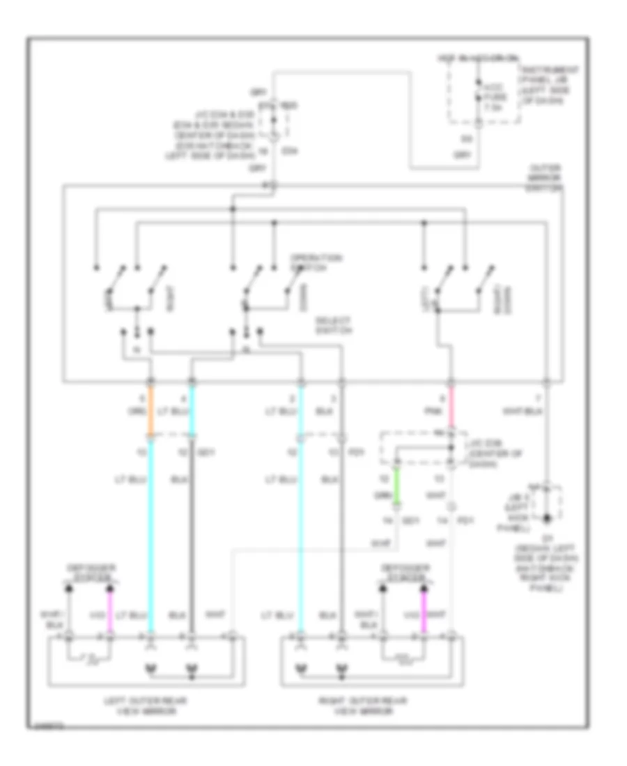
POWER MIRRORS
Power Mirrors Wiring Diagram for Toyota Yaris 2011
List of elements for Power Mirrors Wiring Diagram for Toyota Yaris 2011:
- Acc fuse 7.5a
- D1 (sedan: left side of dash) (hatchback: right kick panel)
- D34
- D35
- Defogger system
- Down
- Down right/
- Fd1
- Gd1
- Hot in acc or on
- Instrument panel j/b (left side of dash)
- J/b 5 (left kick panel)
- J/c d34 & d35 (d34 & d35 sedan: center of dash) (d35 hatchback: left side of dash)
- J/c d38 (center of dash)
- Left
- Left outer rear view mirror
- Operation switch
- Outer mirror switch
- Pnk
- Right
- Right outer rear view mirror
- Select switch
- Up left/
POWER WINDOWS
Power Windows Wiring Diagram, with Rear Power Windows for Toyota Yaris 2011
List of elements for Power Windows Wiring Diagram, with Rear Power Windows for Toyota Yaris 2011:
- (hatchback: left kick panel) (sedan: left side of dash) d1
- (left front door) left front power window regulator motor
- (left kick panel) j/b 5
- (sedan:
- A19
- A21
- A28
- Aa2
- Alt fuse 120a
- B30
- Becu
- Dcty
- Door locks system
- Down
- E17
- Ecu-b fuse 7.5a
- Ecu-ig fuse 10a
- Engine room r/b
- Fd2
- Fusible link block (left rear of engine compt)
- Gd2
- H/b
- H11
- Hj1
- Hot at all times
- Hot in on or start
- Ij1
- Instrument panel j/b (left side of dash)
- Jd1
- Left front door courtesy switch (left front door)
- Left rear power window regulator motor (left rear door)
- Left rear power window switch
- Left side of engine compt)
- Main body ecu
- Pnk
- Power fuse 30a
- Power window master switch
- Pwr relay
- Pws
- Red
- Right front power window regulator motor (right front door)
- Right front power window switch
- Right rear power window regulator motor (right rear door)
- Right rear power window switch
- Rl door fuse 20a
- Rr door fuse 20a
- S/d
Power Windows Wiring Diagram, without Rear Power Windows for Toyota Yaris 2011
List of elements for Power Windows Wiring Diagram, without Rear Power Windows for Toyota Yaris 2011:
- (hatchback: left kick panel) (sedan: left side of dash) d1
- (left front door) left front power window regulator motor
- (left kick panel) j/b 5
- (sedan:
- A21
- A28
- Aa2
- Alt fuse 120a
- B30
- Becu
- Dcty
- Door locks system
- Down
- E17
- Ecu-b fuse 7.5a
- Ecu-ig fuse 10a
- Engine room r/b
- Fd2
- Fusible link block (left rear of engine compt)
- Gd2
- H/b
- H11
- Hot at all times
- Hot in on or start
- Instrument panel j/b (left side of dash)
- Left front door courtesy switch (left front door)
- Left side of engine compt)
- Main body ecu
- Pnk
- Power fuse 30a
- Power window master switch
- Pwr relay
- Pws
- Red
- Right front power window regulator motor (right front door)
- Right front power window switch
- S/d
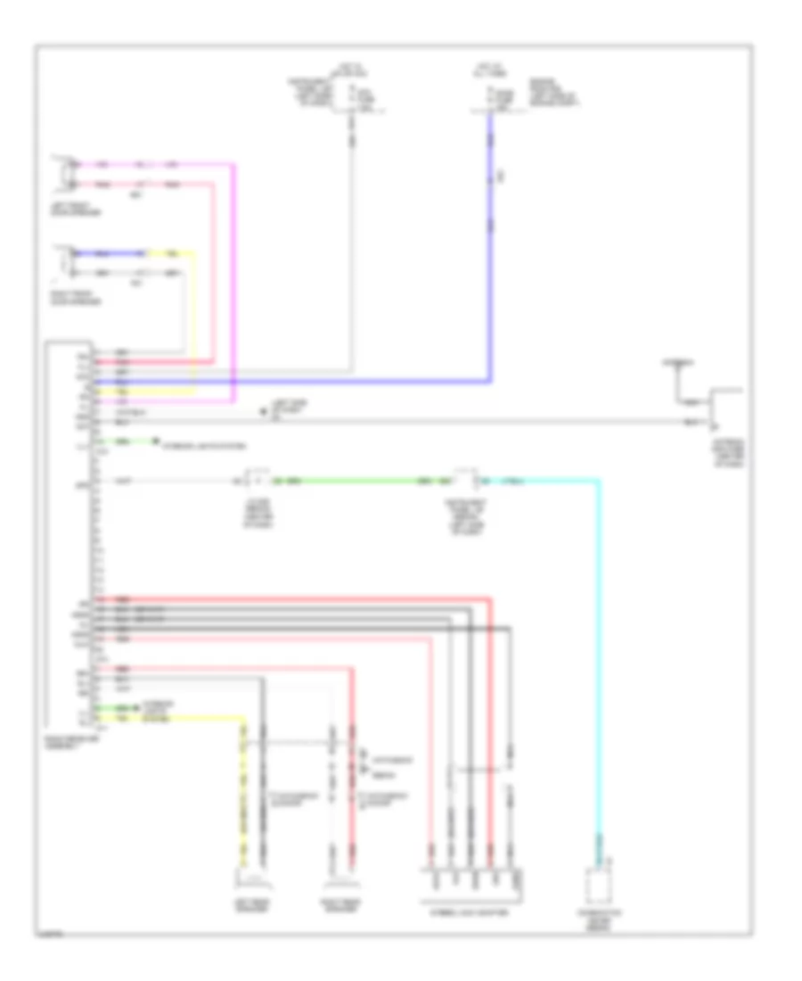
RADIO
Radio Wiring Diagram for Toyota Yaris 2011
List of elements for Radio Wiring Diagram for Toyota Yaris 2011:
- (center of dash)
- (left side of dash)
- (left side of dash) d3
- (or red)
- (sedan)
- Acc
- Acc fuse 7.5a
- Ad2
- Agnd
- Ali
- Alo
- Ant
- Antenna
- Antenna amplifier (center of dash)
- Ari
- Aro
- Asgn
- Auxi
- Auxo
- Combination meter
- D10
- D11
- D14
- D74
- Dome fuse 15a
- Engine room r/b (left side of engine compt)
- Fd1
- Fl+
- Fl-
- Fr+
- Fr-
- Gd1
- Gnd
- Hatchback
- Hatchback 5-door
- Hj1
- Hot at all times
- Hot in on or acc
- Ij1
- Ill+
- Ill-
- Instrument panel j/b
- Instrument panel j/b (left side of dash)
- Interior lights system
- J/c d36
- Jd2
- Jd3
- Left front door speaker
- Left rear speaker
- Nca
- Pnk
- Radio receiver assembly
- Red
- Right front door speaker
- Right rear speaker
- Rl+
- Rl-
- Rr+
- Rr-
- Sedan
- Spd
- Stereo jack adapter
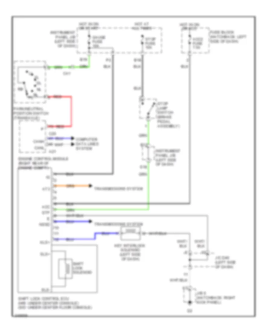
SHIFT INTERLOCK
Shift Interlock Wiring Diagram for Toyota Yaris 2011
List of elements for Shift Interlock Wiring Diagram for Toyota Yaris 2011:
- A21
- Acc
- Acc2 fuse 7.5a
- At3
- B12
- B18
- B19
- C20
- Ca1
- Canh
- Canl
- Computer data lines system
- Engine control module (right rear of engine compt)
- Fuse block (hatchback: left side of dash)
- Gauge fuse 10a
- Hot at all times
- Hot in on or acc
- Hot in on or start
- Instrument panel j/b (left side of dash)
- J/b 6 (hatchback: right kick panel)
- J/c d40 (left side of dash)
- Key interlock solenoid (left side of dash)
- Kls+
- Nssd
- Park/neutral position switch (transaxle)
- Red
- S18
- Shift lock control ecu (h/b: under center console) (s/d: under center floor console)
- Shift lock solenoid
- Sls+
- Sls-
- Stop fuse 10a
- Stop lamp switch (brake pedal assembly)
- Stp
- Transmissions system
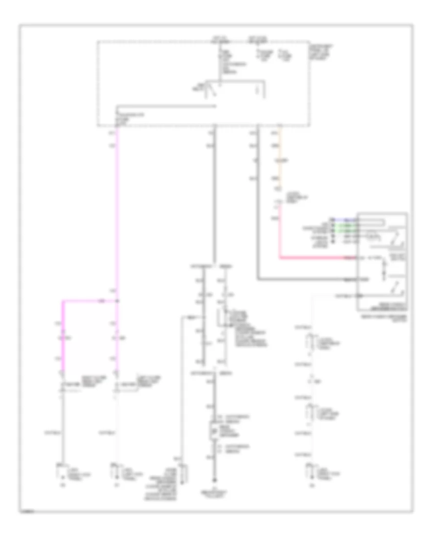
STARTING/CHARGING
Charging Wiring Diagram for Toyota Yaris 2011
List of elements for Charging Wiring Diagram for Toyota Yaris 2011:
- (center of dash)
- (center of dash) running light relay
- (hatchback)
- (right rear of engine compt) engine control module
- (sedan)
- (w/ ptc heater)
- A/c amplifier
- Aa2
- Ae1
- Alt
- Alt fuse 120a
- Alt-s fuse 7.5a
- B19
- Battery
- C20
- C30
- Ca1
- Charge ind
- Chg-
- Combination meter
- D76
- Engine room r/b (left side of engine compt)
- Fusible link block (left rear of engine compt)
- Gauge fuse 10a
- Generator
- Hot at all times
- Hot in on or start
- Instrument panel j/b (left side of dash)
- J/c d39 (center of dash)
- Met fuse 7.5a
- Pnk
- Sedan
- Starting circuit
- W/ drl
- W/o drl
Starting Wiring Diagram for Toyota Yaris 2011
List of elements for Starting Wiring Diagram for Toyota Yaris 2011:
- (clutch pedal assembly) (m/t) clutch start switch
- A1 (left side of engine compt)
- A16
- A21
- Aa2
- Acc
- Ad2
- Ad4
- Am2
- Am2 fuse 15a
- Battery
- C15
- C20
- Ca1
- Ca2
- Diode (starter) (left side of dash)
- Engine control module (right rear of engine compt)
- Engine room j/b (left side of engine compt)
- Engine room r/b (left side of engine compt)
- Hot at all times
- Ignition switch
- Junction connector a25 (sedan: left side of engine compt)
- Junction connector d36 (center of dash)
- Lock
- On off
- Park/neutral position switch (a/t) (transaxle)
- St fuse 30a
- St2
- Sta
- Star
- Start
- Starter
- Starter relay
- Stsw
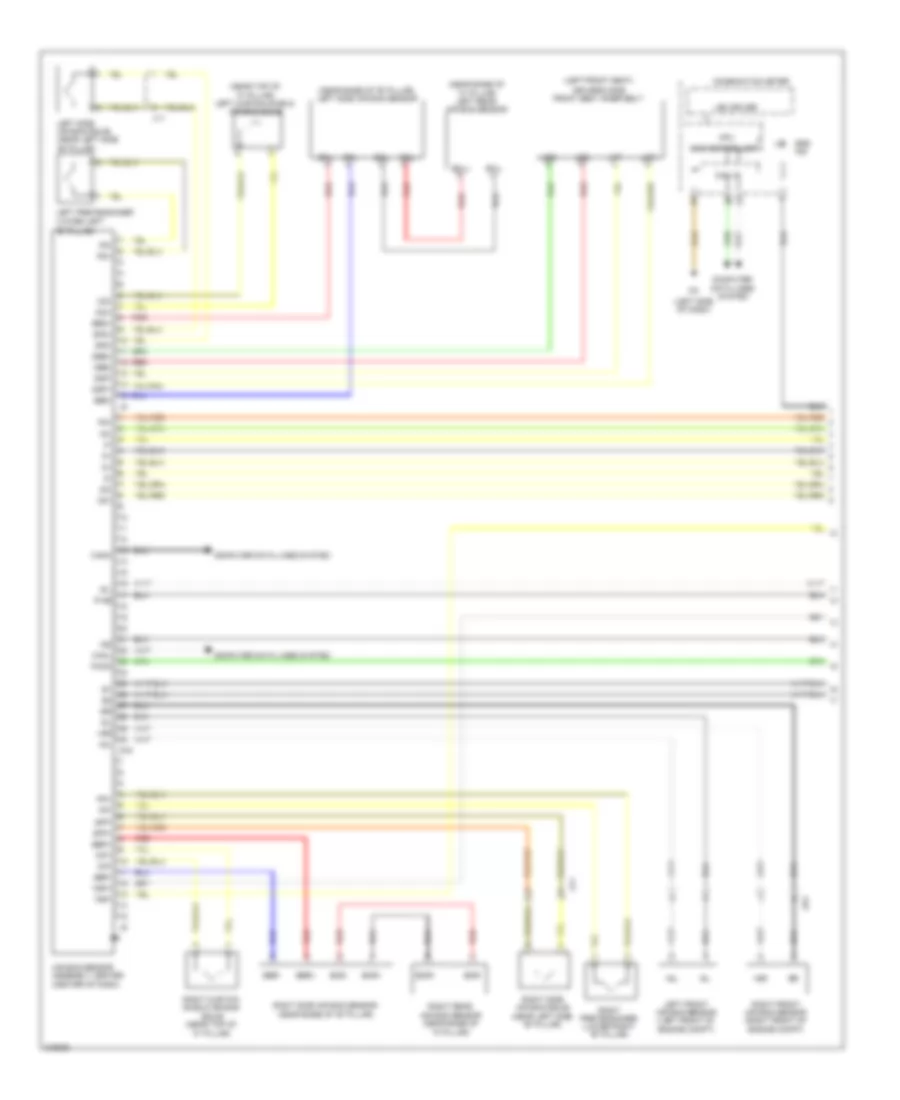
SUPPLEMENTAL RESTRAINTS
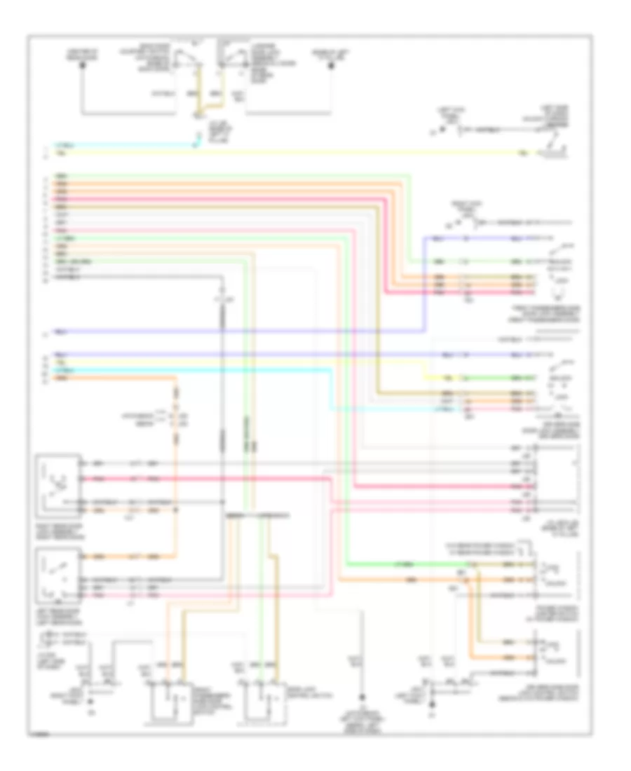
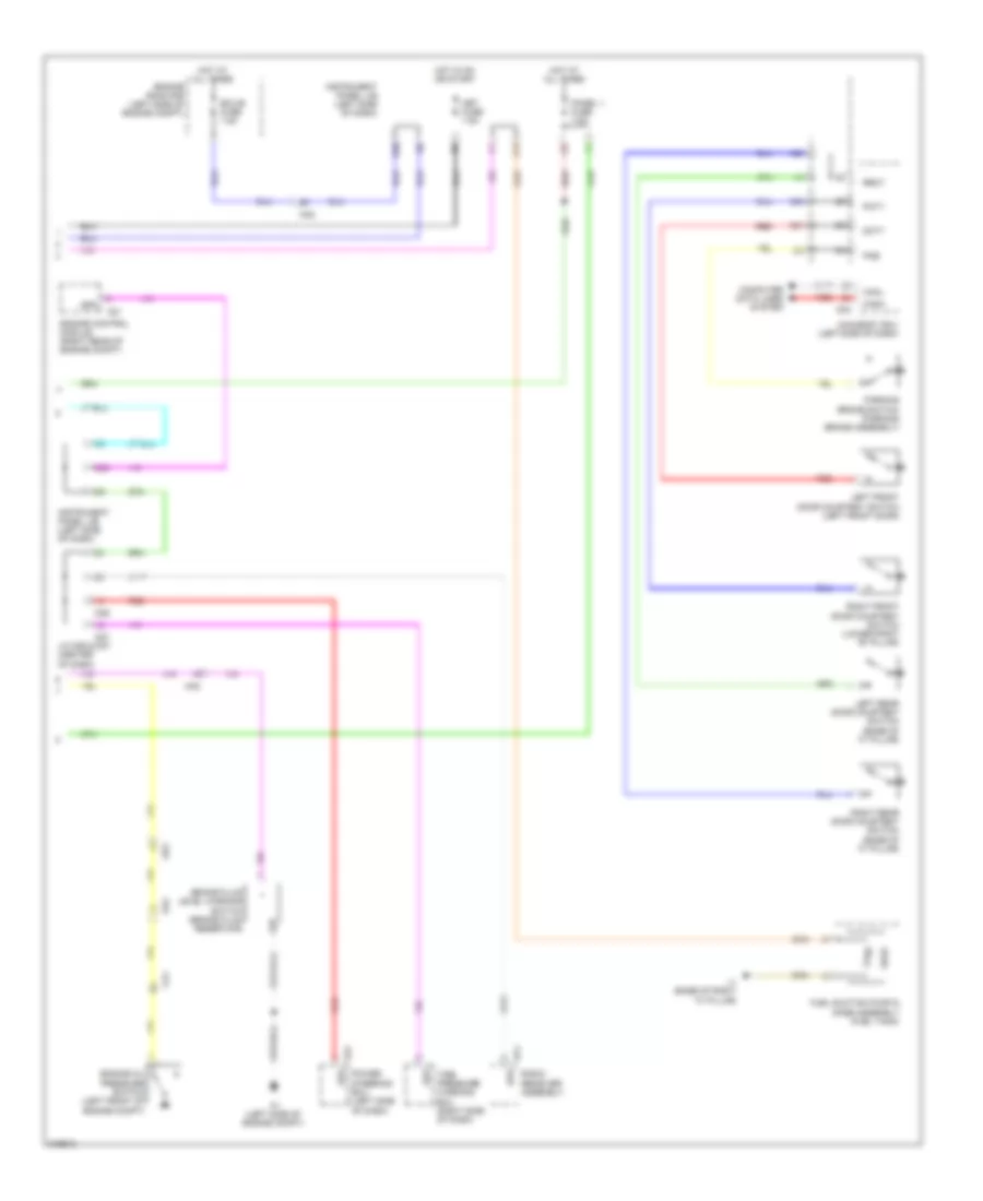
Supplemental Restraints Wiring Diagram (1 of 2) for Toyota Yaris 2011
List of elements for Supplemental Restraints Wiring Diagram (1 of 2) for Toyota Yaris 2011:
- "b" pillar)
- (left front seat)
- (left side of dash)
- (near base of "b" pillar) left side air bag sensor
- (near base of "c" pillar) left rear air bag sensor
- (near left side "b" pillar)
- (near top of "c" pillar) left curtain shield air bag squib
- +sl
- +sr
- -sl
- -sr
- Ad1
- Air bag sensor assembly center (center of dash)
- Bbd+
- Bbd-
- Bbl+
- Bbl-
- Bbp+
- Bbp-
- Bbr+
- Bbr-
- Bcl+
- Bcl-
- Bcr+
- Bcr-
- Can controller
- Can i/f
- Canh
- Canl
- Combination meter
- Computer data lines system
- Cpu
- D16
- D2+
- D2-
- Dbe+
- Dbe-
- Driver's side front seat inner belt
- Dsp+
- Dsp-
- Fsp+
- Fsp-
- Icd+
- Icd-
- Icp+
- Icp-
- Ig2
- Jx1
- Jy1
- Lbe+
- Lbe-
- Led driver
- Left front air bag sensor (left front of engine compt)
- Left pretensioner (lower left
- Left side air bag squib (near left side "b" pillar)
- Lsp+
- Lsp-
- P-ab
- P2+
- P2-
- Paon
- Pd+
- Pd-
- Pp+
- Pp-
- Red
- Right curtain shield air bag squib (near top of "c" pillar)
- Right front air bag sensor (right front of engine compt)
- Right pretensioner (lower right "b" pillar)
- Right rear air bag sensor (near base of "c" pillar)
- Right side air bag sensor (near base of "b" pillar)
- Right side air bag squib
- Sfd+
- Sfd-
- Sfp+
- Sfp-
- Sil
- Srs ind
Supplemental Restraints Wiring Diagram (2 of 2) for Toyota Yaris 2011
List of elements for Supplemental Restraints Wiring Diagram (2 of 2) for Toyota Yaris 2011:
- (front driver's seat)
- (hatchback: left kick panel)
- (sedan: left side of dash)
- (sedan: steering wheel)
- A15
- Aa2
- Air bag squib (front passenger's air bag assembly) (right side of dash)
- Air bag squib (steering wheel pad) (hatchback: steering column)
- B30
- Bgnd
- Bsw
- D2+
- D2-
- D34
- D35
- Data link connector 3 (lower left side of dash)
- Dia
- Dq1
- E14
- E15
- E16
- E17
- E30
- E31
- E32
- Ecu-b fuse 7.5a
- Engine room r/b (left side of engine compt)
- Fsr+
- Fsr-
- Gauge fuse 10a
- Gnd
- H12
- Hatchback
- Hazard warning signal switch (sedan)
- Hot at all times
- Hot in on or start
- Ig+
- Ign fuse 7.5a
- Instrument panel j/b (left side of dash)
- J/c d34 & d35 (d34, d35 sedan: center of dash) (d35 hatchback: left side of dash)
- J/c d36 (center of dash)
- J24
- Jd2
- Left front occupant classification sensor
- Left rear occupant classification sensor (front passenger's seat)
- Met fuse 7.5a
- Occupant classification ecu (under front passenger's seat)
- P-ab
- Paon
- Passenger seat belt warning lamp (hatchback)
- Passenger's seat belt/ air bag ind (on/off)
- Pnk
- Rbe+
- Rbe-
- Red
- Right front occupant classification sensor (front passenger's seat)
- Right front seat inner belt assembly (fight front seat)
- Right rear occupant classification sensor (front passenger's seat)
- S14
- S15
- Sedan
- Sgd1
- Sgd2
- Sgd3
- Sgd4
- Sig1
- Sig2
- Sig3
- Sig4
- Sil
- Spiral cable (hatchback: left side of dash) (sedan: center of dash)
- Svc1
- Svc2
- Svc3
- Svc4
TRANSMISSION
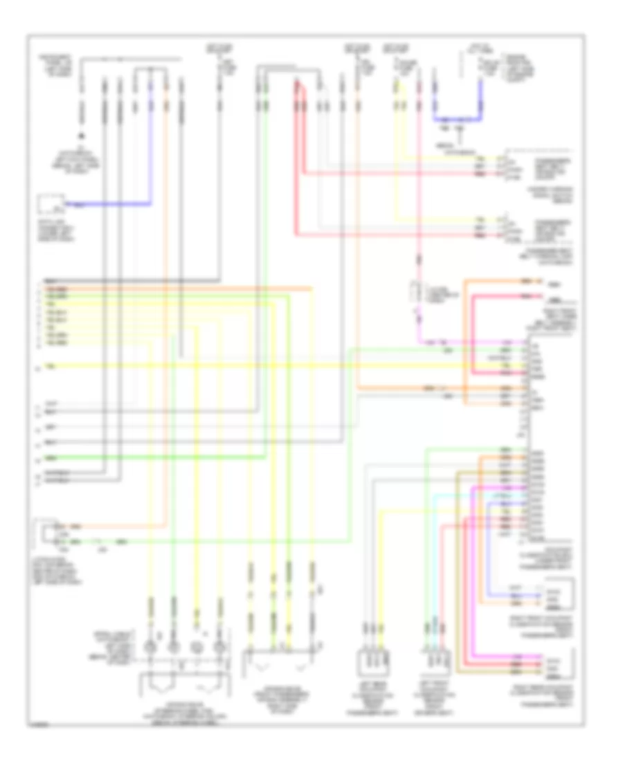
Transmission Wiring Diagram (1 of 2) for Toyota Yaris 2011
List of elements for Transmission Wiring Diagram (1 of 2) for Toyota Yaris 2011:
- (accelerator pedal assembly) accelerator position sensor
- (brake pedal assembly) stop lamp switch
- (left side of engine compt) a1
- (rear of engine) c1
- (rear of engine) c2
- +b2
- +bm
- A1 (left side of engine compt)
- A21
- Aa2
- B18
- B19
- B26
- B27
- B30
- Batt
- C20
- Ca1
- Canh
- Canl
- Computer data lines system
- Ecu-b fuse 7.5a
- Efi fuse 20a
- Efi relay
- Electronically controlled transmission solenoid (transaxle)
- Engine control module (right rear of engine compt)
- Engine room j/b (left side of engine compt)
- Engine room r/b (left side of engine compt)
- Eo1
- Eo2
- Eo3
- Eo4
- Epa
- Epa2
- Etcs fuse 10a
- Etho
- Ethw
- Gauge fuse 10a
- Hatchback
- Hot at all times
- Hot in on or start
- Ign fuse 7.5a
- Igsw
- Instrument panel j/b (left side of dash)
- Meo1
- Mrel
- Ne+
- Ne-
- Nt+
- Nt-
- Odms
- Pnk
- Red
- Sedan
- Slt+
- Slt-
- Slu+
- Slu-
- Spd
- St1-
- Sta
- Star
- Starting/charging system
- Stop fuse 10a
- Stp
- Tach
- Tho1
- Thw
- Vcp2
- Vcpa
- Vpa
- Vpa2
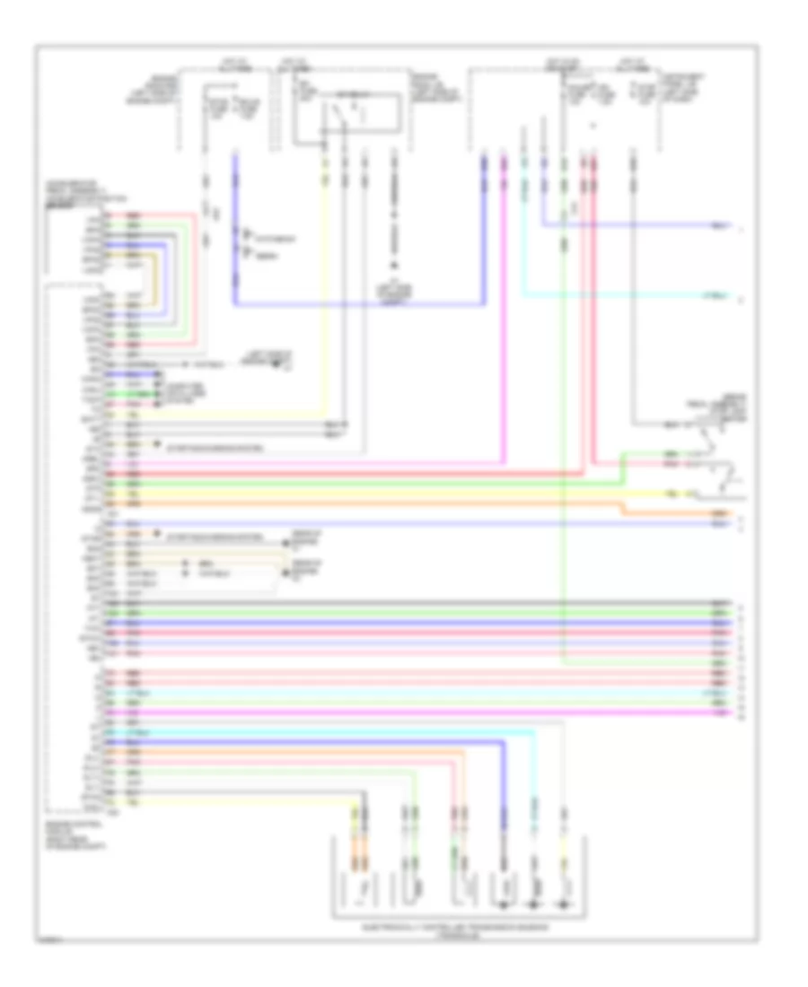
Transmission Wiring Diagram (2 of 2) for Toyota Yaris 2011
List of elements for Transmission Wiring Diagram (2 of 2) for Toyota Yaris 2011:
- (left side of engine compt)
- 5v ic
- A1 (left side of engine compt)
- Aa2
- Ad3
- At3
- B24
- C1 (rear of engine)
- Ca1
- Ca2
- Can controller
- Can i/f
- Combination meter
- Computer data lines system
- Cpu
- Crankshaft position sensor (front of engine)
- D3 (left side of dash)
- Display
- Ecu-ig fuse 10a
- Engine coolant temperature sensor (top rear of engine)
- Hatchback
- Hot in on or start
- I/f
- Ig+
- Instrument panel j/b (left side of dash)
- J/c a25
- Led driver
- Met fuse 7.5a
- Nca
- Nssd
- Park/ neutral position switch (transaxle)
- Pnk
- Red
- Sedan
- Sedan only
- Shift lock control ecu (under center console)
- Speed sensor (transaxle)
- Speed sensor (turbine) (transaxle)
- Speedometer
- Tachometer
- Transmission control switch
WARNING SYSTEMS
Key Reminder & Seat Belt Warning Wiring Diagram for Toyota Yaris 2011
List of elements for Key Reminder & Seat Belt Warning Wiring Diagram for Toyota Yaris 2011:
- (hatchback)
- (left front door) left front door courtesy switch
- (left side of dash) unlock warning switch
- (on/off) air bag ind seat belt/ passenger's
- (sedan)
- 5v ic
- A21
- Aa2
- Acc
- Acc fuse 7.5a
- Air bag ind (on/off)
- Air bag sensor assembly center (center of dash)
- Altb
- B30
- Becu
- Buzzer
- Can controller
- Can i/f
- Canh
- Canl
- Combination meter
- Computer data lines system
- Cpu
- D/l fuse 25a
- D1 (sedan: left side of dash) (hatchback: left kick panel)
- D16
- D3 (left side of dash)
- D33
- D76
- Dbe+
- Dbe-
- Dcty
- Dia
- Door ind
- Driver's seat belt ind
- Driver's side front seat inner belt (left front seat)
- Dsp+
- Dsp-
- E14
- E15
- E16
- E17
- E30
- E32
- Ecu-b fuse 7.5a
- Ecu-ig fuse 10a
- Engine room r/b (left side of engine compt)
- Fsp+
- Fsp-
- Fsr+
- Fsr-
- Gauge fuse 10a
- Gnd
- Gnd1
- Hatchback
- Hazard warning signal switch
- Hot at all times
- Hot in on or acc
- Hot in on or start
- I/f
- Ig+
- Ig2
- Ign fuse 7.5a
- Instrument panel j/b (left side of dash)
- J/b 5 (left kick panel)
- J24
- Jd2
- Ksw
- Lbe+
- Lbe-
- Led driver
- Lsp+
- Lsp-
- Main body ecu
- Met fuse 7.5a
- Occupant classification ecu (under front passenger's seat)
- P-ab
- Paon
- Passenger seat belt warning lamp
- Passenger's seat belt/
- Pbew
- Red
- S14
- S15
- Sedan
- Sil
Tire Pressure Monitoring Wiring Diagram for Toyota Yaris 2011
List of elements for Tire Pressure Monitoring Wiring Diagram for Toyota Yaris 2011:
- (left side of dash) instrument panel j/b
- +5v
- Combination meter
- Computer data lines system
- Cpu
- D3 (left side of dash)
- D36
- D37
- Ecu-ig fuse 10a
- Gnd
- Gnd2
- Hot in on or start
- I/f
- Ind
- Instrument panel j/b (left side of dash)
- J/c d36 & d37 (center of dash)
- Jd3
- Led driver
- Met fuse 7.5a
- Rda
- Red
- Rf5v
- Sil
- Spd
- Tach
- Tire pressure ind
- Tire pressure warning antenna & receiver
- Tire pressure warning ecu
WIPER/WASHER
Front Wiper/Washer Wiring Diagram for Toyota Yaris 2011
List of elements for Front Wiper/Washer Wiring Diagram for Toyota Yaris 2011:
- (hatchback)
- (sedan)
- A1 (left side of engine compt)
- Aa2
- Ad2
- Ad3
- B25
- B36
- Combination meter
- D1 (hatchback: left kick panel) (sedan: left side of dash)
- D76
- E17
- Hot in on or start
- Instrument panel j/b (left side of dash)
- Int
- Met fuse 7.5a
- Mist
- Off
- Solid state
- Washer ind
- Washer switch
- Water level warning switch (right front of engine compt)
- Windshield washer motor (hatchback: washer fluid reservoir) (sedan: right front of engine compt)
- Windshield wiper motor (left rear of engine compt)
- Windshield wiper switch assembly
- Wip fuse 25a
- Wiper relay
- Wiper switch
- Wsh fuse 15a
Rear Wiper/Washer Wiring Diagram for Toyota Yaris 2011
List of elements for Rear Wiper/Washer Wiring Diagram for Toyota Yaris 2011:
- +1r
- A25
- Ad2
- D1 (hatchback: left kick panel) (sedan: left side of dash)
- E17
- Engine compt)
- Hot in on or start
- Instrument panel j/b (left side of dash)
- Jd1
- Mj1
- Mn1
- Off
- On+washer
- Rear washer motor (right front of
- Rear wiper motor assembly (3 door: in tailgate) (5 door: in tailgate assembly)
- Rear wiper/ washer switch
- Rr wip fuse 15a
- Wash
- Windshield wiper switch assembly
- Wsh fuse 15a

 Čeština
 Dansk
Dansk Deutsch
 Ελληνικά
 English
 Español
 Suomi
Suomi Français
 Français
 עברית
עברית Hrvatski
 Magyar
 Italiano
 日本語
日本語 한국어
한국어 Nederlands
 Polski
 Português
 Português
 Română
 Русский
 Slovenčina
 Slovenščina
 Svenska
 Türkçe
 中文 (中国)