ANTI-LOCK BRAKES
Anti-lock Brake Wiring Diagrams for Dodge Neon High Line 1998
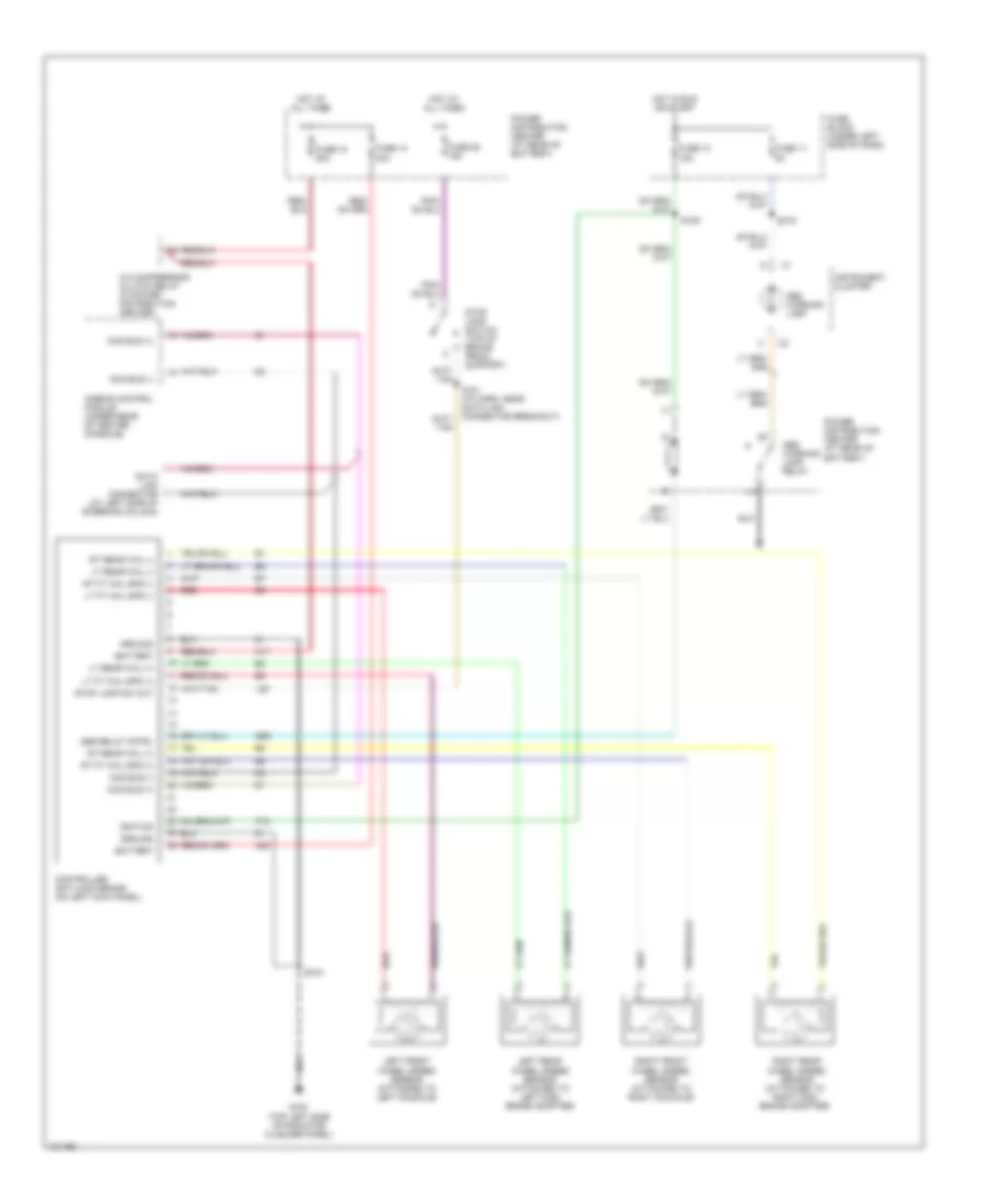
List of elements for Anti-lock Brake Wiring Diagrams for Dodge Neon High Line 1998:
- A/c compressor clutch relay (in power distribution center)
- A17
- A20
- Abs relay cntrl
- Abs warning lamp
- Abs warning lamp relay
- Airbag control module (under rear of center console)
- B58
- Battery
- Ccd bus (+)
- Ccd bus (-)
- Controller anti-lock brake (on left kick panel)
- Data link connector (at left side of steering column)
- F12
- Fuse 10 15a
- Fuse 10 40a
- Fuse 11 5a
- Fuse 18 20a
- Fuse 25 15a
- Fuse block (under left side of dash)
- G100 (top left side of radiator closure panel)
- Ground
- Hot at all times
- Hot in run or start
- Ignition
- Instrument cluster
- L50
- Left front wheel speed sensor (attached to left knuckle)
- Left rear wheel speed sensor (attached to left disc brake adapter)
- Lt ft whl spd (+)
- Lt ft whl spd (-)
- Lt rear whl (+)
- Lt rear whl (-)
- Power distribution center (at rear of battery)
- Red
- Right front wheel speed sensor (attached to right knuckle)
- Right rear wheel speed sensor (attached to right disc brake adapter)
- Rt ft whl spd (+)
- Rt ft whl spd (-)
- Rt rear whl (+)
- Rt rear whl (-)
- S101 (i/p harn, near data link connector breakout)
- S108
- S109
- S219
- Stop lamp sw out
- Stop lamp switch (top of brake pedal support)
 Čeština
 Dansk
Dansk Deutsch
 Ελληνικά
 English
 Español
 Suomi
Suomi Français
 Français
 עברית
עברית Hrvatski
 Magyar
 Italiano
 日本語
日本語 한국어
한국어 Nederlands
 Polski
 Português
 Português
 Română
 Русский
 Slovenčina
 Slovenščina
 Svenska
 Türkçe
 中文 (中国)
 English