ANTI-LOCK BRAKES
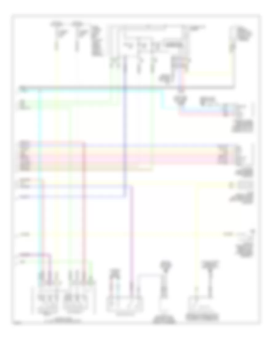
Anti-lock Brakes Wiring Diagram (1 of 2) for Infiniti M45 2004
 https://portal-diagnostov.com/license.html
Automotive Electricians Portal FZCO
Automotive Electricians Portal FZCO
https://portal-diagnostov.com/license.html
https://portal-diagnostov.com/license.html
Automotive Electricians Portal FZCO
Automotive Electricians Portal FZCO
List of elements for Anti-lock Brakes Wiring Diagram (1 of 2) for Infiniti M45 2004:
- (at left side of engine compt) e67
- (unused pins not shown)
- Abs w/l
- Ascd
- Ascd control unit (behind dash, left of steering column)
- Av1(fr)
- Av2(rl)
- Av3(rr)
- Av4(fl)
- Bls
- Can-h
- Can-l
- Computer data lines system
- Data link connector (under left side of dash)
- E21
- E22
- E23
- Ev1(fr)
- Ev2(rl)
- Ev3(rr)
- Ev4(fl)
- Fl mv-av
- Fl mv-ev
- Fl ss
- Fl ss gnd
- Fr mv-av
- Fr mv-ev
- Fr ss
- Fr ss gnd
- Fuse 17 15a
- Fuse 6 10a
- Fuse 7 10a
- Fuse 9 10a
- Fuse block (j/b) 1 (behind left end of dash)
- Gnd
- Gnd1
- Gnd2
- Hot at all times
- Hot in on or start
- J/c 10 (behind upper left end of dash, taped to harness)
- J/c 11 (behind upper right side of dash, taped to harness)
- J/c 7 (behind upper left side of dash, taped to harness)
- J/c 8 (behind lower left side of dash, taped to harness)
- J/c 9 (behind lower left side of dash, taped to harness)
- Left front wheel sensor (at left side of engine compt)
- Left rear wheel sensor (at left rear spindle assembly)
- Lis
- Mav1(mc2)
- Mav2 (mc1)
- Nca
- Pkb sw
- Pnk
- Pressure sensor
- Pri usv
- Pri-mav
- Psm
- Pss
- Psu
- Red
- Right front wheel sensor (at right side of engine compt)
- Right rear wheel sensor (at right rear spindle assembly)
- Rl mv-av
- Rl mv-ev
- Rl ss
- Rl ss gnd
- Rr mv-av
- Rr mv-ev
- Rr ss
- Rr ss gnd
- Rxd
- Sec mav
- Sec usv
- Slip lamp
- Stop lamp switch (on bracket, above the brake pedal)
- Tcs in
- Txd
- Usv1(mc2)
- Usv2(mc1)
- Vcc
- Vdc actuator (at right rear corner of engine compt)
- Vdc off lamp
- Vdc off sw
- Vdc/tcs/abs control unit (behind right kick panel)
- Vout
- W/o icc
- Yrsm
- Yrsrff
- Yrss
- Yrst
- Yrsu
Anti-lock Brakes Wiring Diagram (2 of 2) for Infiniti M45 2004
List of elements for Anti-lock Brakes Wiring Diagram (2 of 2) for Infiniti M45 2004:
- (at right front corner of engine compt) e42
- (behind left side of dash) m25
- 12v
- Abs ind
- Bite
- Brake fluid level switch (left rear of engine compt, on brake fluid reservoir)
- Bs out
- Can-h
- Can-l
- Combination meter
- Computer data lines system
- Drs out
- E55
- E56
- E57
- Fuse, fusible link & relay box (at right front side of engine compt, in engine room box)
- Fusible link f 30a
- Fusible link k 50a
- Gnd
- Ground
- Hot at all times
- Interior lights system
- J/c 25 (behind lower left side of dash) near pass-through grommet)
- J/c 3 (behind upper left end of dash, taped to harness)
- J/c 5 (behind upper left side of dash, taped to harness)
- M41
- M42
- Motor relay
- Nca
- Parking brake switch (behind left side of dash, at park brake assembly)
- Red
- Ref
- Slip ind
- Solenoid valve relay
- Steering wheel angle sensor (under left side of dash, right of steering column)
- Unified meter control unit
- Vdc off ind
- Vdc off switch
- Vdc relay box (at left side of engine compt)
- Yaw rate/ side g sensor (under center console)

 Čeština
 Dansk
Dansk Deutsch
 Ελληνικά
 English
 Español
 Suomi
Suomi Français
 Français
 עברית
עברית Hrvatski
 Magyar
 Italiano
 日本語
日本語 한국어
한국어 Nederlands
 Polski
 Português
 Português
 Română
 Русский
 Slovenčina
 Slovenščina
 Svenska
 Türkçe
 中文 (中国)