ANTI-LOCK BRAKES
Anti-lock Brake Wiring Diagrams for Toyota Pickup DX 1995
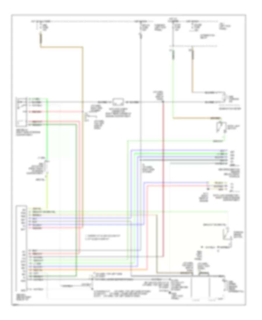
List of elements for Anti-lock Brake Wiring Diagrams for Toyota Pickup DX 1995:
- (ex usa column a/t) i9 (i/p harn, top left side of dash)
- (i/p harn, lower center of dash)
- (i/p harn, right end of dash)
- (i/p harn, right end of dash) i9
- (i/p harn, right kick panel) i14
- (i/p harn, top left side of dash)
- (i/p harn, top right end of dash) i11
- Abs actuator (front right of engine compartment)
- Abs deceleration sensor (below front console)
- Abs ecu (behind right side of i/p)
- Abs fuse 15a
- Abs relay (right side of engine compartment)
- Abs speed sensor (rear differential)
- Abs warning ind
- Anti-lock check connector (right rear corner of engine compartment)
- Bat
- Canada a/t & usa column a/t
- Combination meter
- Data link connector 1 (right side of engine compartment)
- Ecu-ig fuse 20a
- Fuse box (left kick panel)
- G117 (right rear of engine)
- G200 (left kick panel)
- Gauge fuse 10a
- Gnd
- Gs1
- Gs2
- Gst
- Hot at all times
- Hot in run
- I12 (a/t) i9 (m/t)
- I3 (canada m/t) i6 (usa m/t) i9 (a/t)
- I6 (usa column a/t) (i/p harn, lower center of dash)
- I9 (i/p harn, right side of dash)
- Ig1
- Integration relay
- J/b 1 (left kick panel)
- M/t & usa floor a/t
- Parking brake switch
- Pkb
- Rr+
- Rr-
- Rss
- Stop fuse 15a
- Stop light switch
- Stp
 Čeština
 Dansk
Dansk Deutsch
 Ελληνικά
 English
 Español
 Suomi
Suomi Français
 Français
 עברית
עברית Hrvatski
 Magyar
 Italiano
 日本語
日本語 한국어
한국어 Nederlands
 Polski
 Português
 Português
 Română
 Русский
 Slovenčina
 Slovenščina
 Svenska
 Türkçe
 中文 (中国)
 English