ANTI-THEFT
Anti-theft Wiring Diagram for Honda Odyssey EX 1998
 https://portal-diagnostov.com/license.html
Automotive Electricians Portal FZCO
Automotive Electricians Portal FZCO
https://portal-diagnostov.com/license.html
https://portal-diagnostov.com/license.html
Automotive Electricians Portal FZCO
Automotive Electricians Portal FZCO
List of elements for Anti-theft Wiring Diagram for Honda Odyssey EX 1998:
- (on center front of engine compartment, forward of radiator) hood switch
- 10a
- Antenna
- Auxiliary fuse holder (on left side of underdash fuse/relay box)
- C262
- C263
- C402
- C403
- C405
- C503
- C57
- C601
- C911 (option connector)
- Disarm/valet switch
- Door locks system
- Door locks system (w/ keyless)
- Door locks system (w/keyless entry) (ex models)
- Driver's door switch (in left front "b" pillar)
- Exterior & interior lights systems
- Front passenger's door switch (in right front "b" pillar)
- G108 (center of radiator support)
- G200 (behind left kick panel)
- G411 (left side of tailgate)
- Gauge assembly
- Glass breakage microphone
- Horns system
- Hot at all times
- Hot in on or start
- Ign. sw fuse 16 50a
- Ignition key switch (closed with key in ignition)
- Instrument cluster system
- Interior lights system
- Interior lights system (ceiling light)
- J/c
- J/c c469 (under right side of dash)
- Left rear door switch (on left rear quarter panel)
- Light flasher relay
- Red
- Right rear door switch (on right rear quarter panel)
- Safety indicator
- Security control unit (below driver's seat)
- Security in-line fuse holder (above left kick panel)
- Security indicator
- Siren (optional)
- Small light fuse 32 15a
- Steering lock
- Tailgate latch switch (closed w/tailgate open)
- Underdash fuse/relay box (behind left kick panel)
- Underhood fuse/relay box (on right rear corner of engine compartment)
- Warning systems
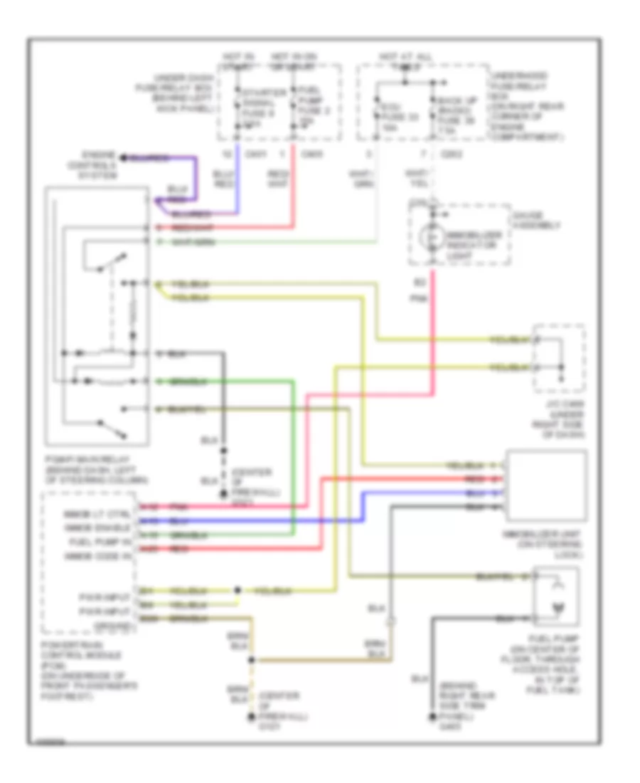
Immobilizer Wiring Diagram for Honda Odyssey EX 1998
List of elements for Immobilizer Wiring Diagram for Honda Odyssey EX 1998:
- (behind right rear side trim panel) g403
- (center of firewall) g121
- A12
- A13
- A15
- A25
- B20
- Back up (radio) fuse 39 7.5a
- C10
- C262
- C401
- C405
- Ecu fuse 33 10a
- Engine controls system
- Fuel pump (on center of floor, through access hole, in top of fuel tank)
- Fuel pump fuse 2 15a
- Fuel pump in
- Gauge assembly
- Ground
- Hot at all times
- Hot in on or start
- Hot in start
- Immob code in
- Immob enable
- Immob lt ctrl
- Immobilizer indicator light
- Immobilizer unit (on steering lock)
- J/c c469 (under right side of dash)
- Pgm-fi main relay (behind dash, left of steering column)
- Pnk
- Powertrain control module (pcm) (on underside of front passenger's footrest)
- Pwr input
- Red
- Starter signal fuse 9 7.5a
- Under dash fuse/relay box (behind left kick panel)
- Underhood fuse/relay box (on right rear corner of engine compartment)

 Čeština
 Dansk
Dansk Deutsch
 Ελληνικά
 English
 Español
 Suomi
Suomi Français
 Français
 עברית
עברית Hrvatski
 Magyar
 Italiano
 日本語
日本語 한국어
한국어 Nederlands
 Polski
 Português
 Português
 Română
 Русский
 Slovenčina
 Slovenščina
 Svenska
 Türkçe
 中文 (中国)