COMPUTER DATA LINES
Computer Data Lines Wiring Diagram, with Stripped Chassis for Ford E-350 Super Duty XLT 2014
 https://portal-diagnostov.com/license.html
Automotive Electricians Portal FZCO
Automotive Electricians Portal FZCO
https://portal-diagnostov.com/license.html
https://portal-diagnostov.com/license.html
Automotive Electricians Portal FZCO
Automotive Electricians Portal FZCO
List of elements for Computer Data Lines Wiring Diagram, with Stripped Chassis for Ford E-350 Super Duty XLT 2014:
- (engine control sensor wiring harness, near breakout to c110)
- (engine control sensor wiring harness, near breakout to c110) s111
- (main wiring harness, near breakout to traction control switch)
- (main wiring harness, near breakout to traction control switch) s258
- (mounted to front of left chassis frame rail) anti-lock brake system (abs) module
- 6.8l
- Battery junction box (bjb) (mounted to front of left chassis frame rail)
- C1551b
- C175b
- C2280b
- C291
- Cdb08
- Data link connector (dlc) (left center of dash)
- Except 6.8l
- Feps
- Fuse 15a
- G205 (left side of dash)
- G207 (center of dash)
- Gd114
- Gd133
- Hot at all times
- Hs can +
- Hs can -
- Hs can+
- Hs can-
- Instrument panel cluster (ipc)
- Micro
- Ms can+
- Ms can-
- Powertrain control module (pcm) (above front center of engine)
- S250
- S255 (main wiring harness, near breakout to traction control switch)
- S256
- S257 (main wiring harness, near breakout to traction control switch)
- Sbb42
- Smart junction box (sjb) (left side of dash)
- Vdb04
- Vdb05
- Vdb06
- Vdb07
- Vdbo4
- Vdbo5
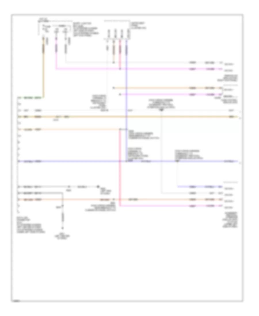
Computer Data Lines Wiring Diagram, without Stripped Chassis with Navigation (1 of 2) for Ford E-350 Super Duty XLT 2014
List of elements for Computer Data Lines Wiring Diagram, without Stripped Chassis with Navigation (1 of 2) for Ford E-350 Super Duty XLT 2014:
- (main wiring harness, in breakout to accessory protocol interface module (apim)) s266
- (main wiring harness, in breakout to accessory protocol interface module (apim)) s267
- (main wiring harness, in breakout to instrument panel cluster (ipc)) s224
- (main wiring harness, in breakout to instrument panel cluster (ipc)) s225
- (main wiring harness, near breakout to overdrive cancel switch)
- Accessory protocol interface module (apim) (w/ sync) (upper left side of dash)
- Audio control module (acm)
- C219
- C2280a
- C2280b
- C240b
- Cdb08
- Data link connector (dlc) (w/ stripped chassis: left center of dash) (w/o stripped chassis: under left side of dash)
- Fuse 15a
- G201 (left center of dash)
- G202 (left end of dash)
- Gd114
- Gd115
- Hot at all times
- Hs can +
- Hs can -
- Instrument panel cluster (ipc)
- Micro
- Ms can +
- Ms can -
- Parking aid module (pam) (right kick panel)
- S228
- S229 (main wiring harness, near breakout to overdrive cancel switch)
- S263
- S264
- Sbp20
- Smart junction box (sjb) (w/ stripped chassis: left side of dash) (w/o stripped chassis: left kick panel)
- Vdb04
- Vdb05
- Vdb06
- Vdb07
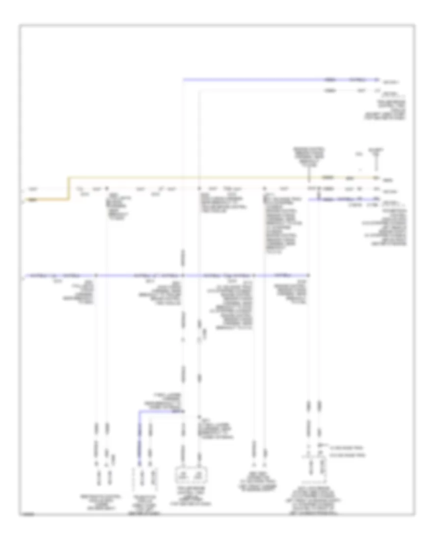
Computer Data Lines Wiring Diagram, without Stripped Chassis with Navigation (2 of 2) for Ford E-350 Super Duty XLT 2014
List of elements for Computer Data Lines Wiring Diagram, without Stripped Chassis with Navigation (2 of 2) for Ford E-350 Super Duty XLT 2014:
- (engine control sensor wiring harness, near breakout to c192)
- (left front corner
- (main wiring harness, near breakout to trailer brake control (tbc) module)
- (t-box jumper harness, near breakout to modem antenna) s270
- 6.8l
- Abs test connector (w/ advance trac)
- Anti-lock brake system (abs) module (w/o stripped chassis: left front of engine compt) (w/ stripped chassis: mounted to front of left chassis frame rail)
- C1551b
- C175b
- C210
- C2108
- C219
- C310b
- Cdb08
- Except 6.8l
- Feps
- Harness, near breakout to modem antenna)
- Hs can +
- Hs can -
- Hsc1-a
- Hsc1-c
- Hsc2-c
- Of engine compt)
- Powertrain control module (pcm) (w/o stripped chassis: left rear of engine compt) (w/ stripped chassis: above front center of engine)
- Restraints control module (rcm) (under driver's seat)
- S112 (w/ advance trac) (w/o stripped chassis: engine control sensor wiring harness, near breakout to g105) (w/ stripped chassis: engine control sensor wiring harness, near breakout to c110)
- S126 (engine control sensor wiring harness, near breakout to c192)
- S127
- S221
- S222 (main wiring harness, near breakout to trailer brake control (tbc) module)
- S271 (t-box jumper hsc2-a
- S301 (taillights wiring harness, near breakout to g203)
- S302
- Telematics module (crew chief) (top left center of dash)
- Trailer brake control (tbc) module (crew chief) (top center of dash)
- Trailer brake control (tbc) module (except crew chief) (top center of dash)
- Vdb04
- Vdb05
- W/ advance trac
- W/o advance trac
Computer Data Lines Wiring Diagram, without Stripped Chassis without Navigation (1 of 2) for Ford E-350 Super Duty XLT 2014
List of elements for Computer Data Lines Wiring Diagram, without Stripped Chassis without Navigation (1 of 2) for Ford E-350 Super Duty XLT 2014:
- (main wiring harness, in breakout to accessory protocol interface module (apim)) s266
- (main wiring harness, in breakout to instrument panel cluster (ipc)) s224
- (main wiring harness, in breakout to instrument panel cluster (ipc)) s225
- (main wiring harness, near breakout to overdrive cancel switch)
- (right kick panel)
- Accessory protocol interface module (apim) (w/ sync) (upper left side of dash)
- Audio control module (acm)
- C219
- C2280a
- C2280b
- C2408b
- C240b
- Cdb08
- Data link connector (dlc) (w/o stripped chassis: under left side of dash) (w/ stripped chassis: left center of dash)
- Fuse 15a
- G201 (left center of dash)
- G202 (left end
- Gd114
- Gd115
- Global positioning system module (gpsm) (w/ sync) (behind right side of instrument cluster)
- Hot at all times
- Hs can +
- Hs can -
- In dash computer
- Instrument panel cluster (ipc)
- Micro
- Ms can +
- Ms can -
- Of dash)
- Parking aid module (pam)
- S228
- S229 (main wiring harness, near breakout to overdrive cancel switch)
- S263
- S264
- S267 (main wiring harness, in breakout to accessory protocol interface module (apim))
- Sbp20
- Smart junction box (sjb) (w/o stripped chassis: left kick panel) (w/ stripped chassis: left side of dash)
- Vdb04
- Vdb05
- Vdb06
- Vdb07
Computer Data Lines Wiring Diagram, without Stripped Chassis without Navigation (2 of 2) for Ford E-350 Super Duty XLT 2014
List of elements for Computer Data Lines Wiring Diagram, without Stripped Chassis without Navigation (2 of 2) for Ford E-350 Super Duty XLT 2014:
- (engine control sensor wiring harness, near breakout to c192)
- (left front corner
- (main wiring harness, near breakout to trailer brake control (tbc) module)
- (t-box jumper harness, near breakout to modem antenna)
- (taillights wiring harness, near breakout to g203)
- 6.8l
- Abs test connector (w/ advance trac)
- Anti-lock brake system (abs) module (w/o stripped chassis: left front of engine compt) (w/ stripped chassis: mounted to front of left chassis frame rail)
- C1551b
- C175b
- C210
- C2108
- C219
- C310b
- Cdb08
- Except 6.8l
- Feps
- Harness, near breakout to modem antenna)
- Hs can +
- Hs can -
- Hsc1-a
- Hsc1-c
- Hsc2-c
- Of engine compt)
- Powertrain control module (pcm) (w/o stripped chassis: left rear of engine compt) (w/ stripped chassis: above front center of engine)
- Restraints control module (rcm) (under driver's seat)
- S112 (w/ advance trac) (w/o stripped chassis: engine control sensor wiring harness, near breakout to g105) (w/ stripped chassis: engine control sensor wiring harness, near breakout to c110)
- S126 (engine control sensor wiring harness, near breakout to c192)
- S127
- S221
- S222 (main wiring harness, near breakout to trailer brake control (tbc) module)
- S270
- S271 (t-box jumper hsc2-a
- S301 (taillights wiring harness, near breakout to g203)
- S302
- Telematics module (crew chief) (top left center of dash)
- Trailer brake control (tbc) module (crew chief) (top center of dash)
- Trailer brake control (tbc) module (except crew chief) (top center of dash)
- Vdb04
- Vdb05
- W/ advance trac
- W/o advance trac

 Čeština
 Dansk
Dansk Deutsch
 Ελληνικά
 English
 Español
 Suomi
Suomi Français
 Français
 עברית
עברית Hrvatski
 Magyar
 Italiano
 日本語
日本語 한국어
한국어 Nederlands
 Polski
 Português
 Português
 Română
 Русский
 Slovenčina
 Slovenščina
 Svenska
 Türkçe
 中文 (中国)