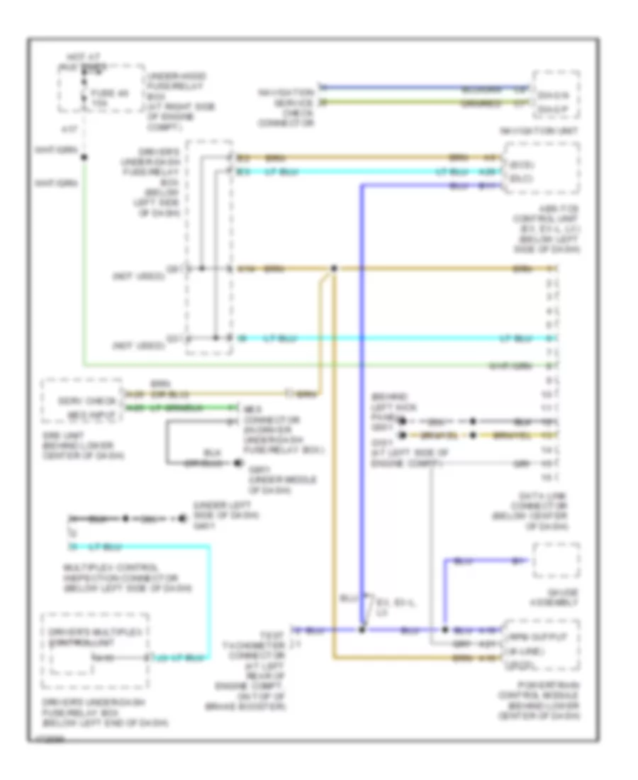
COMPUTER DATA LINES
Computer Data Lines Wiring Diagram for Honda Odyssey LX 2003
List of elements for Computer Data Lines Wiring Diagram for Honda Odyssey LX 2003:
- (behind left kick panel) g501
- (dlc)
- (in driver under-dash fuse/relay box)
- (k-line)
- (not used)
- (scs)
- (under left side of dash) g401
- A10
- A15
- A17
- A19
- A21
- A25
- A26
- Abs-tcs control unit (ex, ex-l, lx) (below left side of dash)
- B11
- Data link connector (below center of dash)
- Diag n
- Diag p
- Driver's multiplex control unit
- Driver's under-dash fuse/relay box (below left end of dash)
- Driver's under-dash fuse/relay box (below left side of dash)
- Ex, ex-l, lx
- Fuse 46 15a
- G101 (at left side of engine compt)
- G851 (under middle of dash)
- Gauge assembly
- Hot at all times
- K14
- Mes connector
- Mes input
- Multiplex control inspection connector (below left side of dash)
- Navigation service check connector
- Navigation unit
- Powertrain control module (behind lower center of dash)
- Rpm output
- Serv check
- Srs unit (behind lower center of dash)
- Test tachometer connector (at left rear of engine compt, on top of brake booster)
- Under-hood fuse/relay box (at right side of engine compt)
 Čeština
 Dansk
Dansk Deutsch
 Ελληνικά
 English
 Español
 Suomi
Suomi Français
 Français
 עברית
עברית Hrvatski
 Magyar
 Italiano
 日本語
日本語 한국어
한국어 Nederlands
 Polski
 Português
 Português
 Română
 Русский
 Slovenčina
 Slovenščina
 Svenska
 Türkçe
 中文 (中国)
 English