COOLING FAN
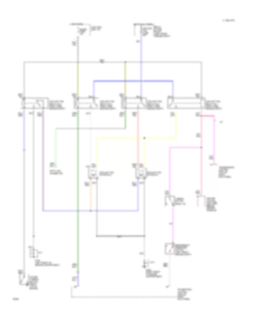
Cooling Fan Wiring Diagram for Mazda RX-7 1994
List of elements for Cooling Fan Wiring Diagram for Mazda RX-7 1994:
- (right i/p)
- 1994 vftc c
- A/t
- Coolant fan motor n0.1
- Coolant fan motor n0.2
- Coolant fan relay no.1 (right side engine compt)
- Coolant fan relay no.2 (right side engine compt)
- Coolant fan relay no.3 (right side engine compt)
- Coolant fan relay no.4 (right side engine compt)
- Cooling fan fuse 60a
- Data link connector
- G108 (left front of engine compartment)
- G109 (right front of engine compartment)
- Heater control amplifier (behind center console)
- Hot at all times
- Hot in run
- J/c 1
- J/c 2
- Joint box (left i/p)
- Meter fuse 15a
- Powertrain control module (right kick panel)
- Refrigerant pressure switch (left front engine compt)
- Relay & fuse block (left front engine compt)
- Thermo- switch
- Transmission control module (right kick panel)
- Water thermo- switch (front top of engine)
 Čeština
 Dansk
Dansk Deutsch
 Ελληνικά
 English
 Español
 Suomi
Suomi Français
 Français
 עברית
עברית Hrvatski
 Magyar
 Italiano
 日本語
日本語 한국어
한국어 Nederlands
 Polski
 Português
 Português
 Română
 Русский
 Slovenčina
 Slovenščina
 Svenska
 Türkçe
 中文 (中国)
 English