CRUISE CONTROL
Cruise Control Wiring Diagram, with Navigation (1 of 2) for Honda Pilot VP 2008
 https://portal-diagnostov.com/license.html
Automotive Electricians Portal FZCO
Automotive Electricians Portal FZCO
https://portal-diagnostov.com/license.html
https://portal-diagnostov.com/license.html
Automotive Electricians Portal FZCO
Automotive Electricians Portal FZCO
List of elements for Cruise Control Wiring Diagram, with Navigation (1 of 2) for Honda Pilot VP 2008:
- "on" indicator
- (2wd) (4wd)
- A11
- A17
- A18
- A20
- A24
- A25
- A34
- A35
- A36
- App sensor (right side of engine compt)
- B12
- B14
- B16
- B17
- B18
- B19
- B33
- B34
- B40
- Braided wire
- Brake pedal position switch (top of brake pedal arm)
- C17
- C40
- Communication
- Computer data lines system
- Cruise control main switch
- Cruise control main switch light
- Cruise control main switch/ vsa off switch
- Drive input
- Driver's under-dash fuse/relay box (below left end of dash)
- Fuse 47 20a
- Fuse 6 15a
- G101 (rear of engine)
- G401 (behind upper left end of dash)
- Ground
- Horn relay
- Hot at all times
- Hot in on or start
- Interior lights system
- Junction connector c104 (rear of engine compt)
- Junction connector c104 c105 (c105: top of transmission, (c104: rear of engine compt)
- M14
- Output shaft (counter shaft) speed sensor (on top of transaxle)
- Passenger's under-dash fuse/relay box (behind right kick panel)
- Powertrain control module (pcm) (right side of engine compt)
- Red
- Reference voltage
- Relay control
- Relay input
- S4 (thermal joint)
- Sensor ground
- Sensor input
- Sensor voltage
- Signal high
- Signal low
- Switch input
- Throttle actuator(+)
- Throttle actuator(-)
- Tp sensor a signal
- Tp sensor b signal
- Tp sensor/throttle actuator (on side of throttle body assembly)
- Under-hood fuse/relay box right side of engine compt)
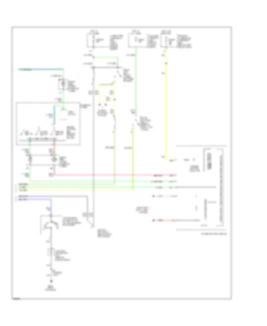
Cruise Control Wiring Diagram, with Navigation (2 of 2) for Honda Pilot VP 2008
 https://portal-diagnostov.com/license.html
Automotive Electricians Portal FZCO
Automotive Electricians Portal FZCO
https://portal-diagnostov.com/license.html
https://portal-diagnostov.com/license.html
Automotive Electricians Portal FZCO
Automotive Electricians Portal FZCOList of elements for Cruise Control Wiring Diagram, with Navigation (2 of 2) for Honda Pilot VP 2008:
- A11
- A17
- Auxiliary fuse box (left side of engine compt)
- B11
- B12
- B13
- B25
- Cable reel (inside steering wheel)
- Cancel switch
- Computer data lines system
- Cruise control dimming circuit
- Cruise control indicator
- Cruise control set/ resume/ cancel switch
- Driver's under-dash fuse/relay box (below left end of dash)
- Engine controls
- Etcs control relay (behind right kick panel)
- F-can transceiver
- Fuse 46 15a
- Fuse 7 15a
- Fuse 9 10a
- G101 (rear of engine)
- Gauge control module
- Horn switch
- Hot at all times
- Hot in on or start
- Ignition coil relay (behind right kick panel)
- Junction connector c104 (rear of engine compt)
- Pgm-fi main relay 1 (under left side of dash)
- Red
- Resume switch
- Set switch
- Steering wheel
- System
- Transmission range switch (on transmission end cover)
- Under hood fuse/relay box (right side of engine compt)
Cruise Control Wiring Diagram, without Navigation (1 of 2) for Honda Pilot VP 2008
 https://portal-diagnostov.com/license.html
Automotive Electricians Portal FZCO
Automotive Electricians Portal FZCO
https://portal-diagnostov.com/license.html
https://portal-diagnostov.com/license.html
Automotive Electricians Portal FZCO
Automotive Electricians Portal FZCOList of elements for Cruise Control Wiring Diagram, without Navigation (1 of 2) for Honda Pilot VP 2008:
- "on" indicator
- (2wd) (4wd)
- A11
- A17
- A18
- A20
- A24
- A25
- A34
- A35
- A36
- App sensor (right side of engine compt)
- B12
- B14
- B16
- B17
- B18
- B19
- B33
- B34
- B40
- Braided wire
- Brake pedal position switch (top of brake pedal arm)
- C17
- C40
- Communication
- Computer data lines system
- Cruise control main switch
- Cruise control main switch light
- Cruise control main switch/ vsa off switch
- Drive input
- Driver's under-dash fuse/relay box (below left end of dash)
- Fuse 47 20a
- Fuse 6 15a
- G101 (rear of engine)
- G401 (behind upper left end of dash)
- Ground
- Horn relay
- Hot at all times
- Hot in on or start
- Interior lights system
- Junction connector c104 (rear of engine compt)
- Junction connector c104 c105 (c105: top of transmission, (c104: rear of engine compt)
- M14
- Output shaft (counter shaft) speed sensor (on top of transaxle)
- Passenger's under-dash fuse/relay box (behind right kick panel)
- Powertrain control module (pcm) (right side of engine compt)
- Red
- Reference voltage
- Relay control
- Relay input
- S4 (thermal joint)
- Sensor ground
- Sensor input
- Sensor voltage
- Signal high
- Signal low
- Switch input
- Throttle actuator(+)
- Throttle actuator(-)
- Tp sensor a signal
- Tp sensor b signal
- Tp sensor/throttle actuator (on side of throttle body assembly)
- Under-hood fuse/relay box (right side of engine compt)
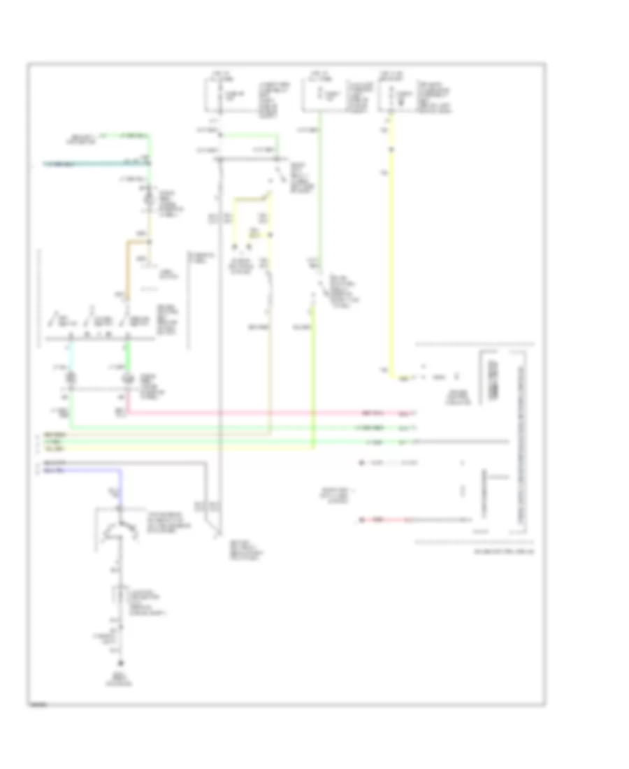
Cruise Control Wiring Diagram, without Navigation (2 of 2) for Honda Pilot VP 2008
 https://portal-diagnostov.com/license.html
Automotive Electricians Portal FZCO
Automotive Electricians Portal FZCO
https://portal-diagnostov.com/license.html
https://portal-diagnostov.com/license.html
Automotive Electricians Portal FZCO
Automotive Electricians Portal FZCOList of elements for Cruise Control Wiring Diagram, without Navigation (2 of 2) for Honda Pilot VP 2008:
- A11
- A17
- Auxiliary fuse box (left side of engine compt)
- B11
- B12
- B13
- B25
- Cable reel (inside steering wheel)
- Cancel switch
- Computer data lines system
- Cruise control dimming circuit
- Cruise control indicator
- Cruise control set/ resume/ cancel switch
- Driver's under-dash fuse/relay box (below left end of dash)
- Engine controls
- Etcs control relay (behind right kick panel)
- F-can transceiver
- Fuse 46 15a
- Fuse 7 15a
- Fuse 9 10a
- G101 (rear of engine)
- Gauge control module
- Horn switch
- Hot at all times
- Hot in on or start
- Ignition coil relay (behind right kick panel)
- Junction connector c104 (rear of engine compt)
- Lx, vp
- Pgm-fi main relay 1 (under left side of dash)
- Red
- Resume switch
- S2 (thermal joint)
- Security connector
- Set switch
- Steering wheel
- System
- Transmission range switch (on transmission end cover)
- Under hood fuse/relay box (right side of engine compt)

 Čeština
 Dansk
Dansk Deutsch
 Ελληνικά
 English
 English
 Español
 Suomi
Suomi Français
 Français
 עברית
עברית Hrvatski
 Magyar
 Italiano
 日本語
日本語 Nederlands
 Polski
 Português
 Português
 Română
 Русский
 Slovenčina
 Slovenščina
 Svenska
 Türkçe
 中文 (中国)
