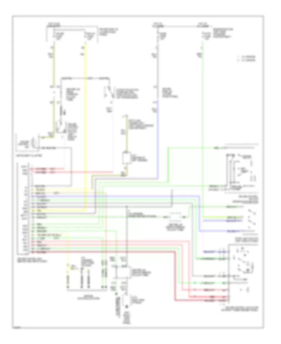
CRUISE CONTROL
Cruise Control Wiring Diagram for Toyota 4Runner SR5 1996
List of elements for Cruise Control Wiring Diagram for Toyota 4Runner SR5 1996:
- (a/t)
- (i/p harness, right side of dash) i11
- (m/t)
- 2.7l engine
- 3.4l engine
- Batt
- C11
- C12
- Cancel
- Ccs
- Center j/b (near steering column tube)
- Cms
- Cruise
- Cruise control actuator (on right inner fender panel)
- Cruise control clutch switch (left side of dash)
- Cruise control ecu (behind center of dash)
- Cruise control ind
- Cruise control switch (combination switch)
- D position switch (park/neutral position switch) (on transmission)
- Data link connector 1 (left side of engine compartment)
- Dome fuse 15a
- Driver side j/b (lower finish panel)
- E10
- E15
- E18
- Ect
- Ecu-ig fuse 10a
- Engine controls system
- Engine room r/b (left side of engine compartment)
- F13
- G201 (right side cowl panel)
- Gauge fuse 10a
- Gnd
- Hot at all times
- Hot in on and start
- I7 (i/p harness, upper center of dash)
- Idl
- Igb
- Instrument cluster
- J/c 1 (center of left fender)
- J/c 9 (right end of dash)
- J12
- N&c
- Pkb
- Red
- Resume/ accel
- Set/ coast
- Spd
- Stop fuse 10a
- Stop light switch (left side of dash)
- Stp+
- Stp-
- To instrument cluster system
- Vr1
- Vr2
- Vr3
 Čeština
 Dansk
Dansk Deutsch
 Ελληνικά
 English
 English
 Español
 Suomi
Suomi Français
 Français
 עברית
עברית Hrvatski
 Magyar
 Italiano
 日本語
日本語 한국어
한국어 Nederlands
 Polski
 Português
 Português
 Română
 Slovenčina
 Slovenščina
 Svenska
 Türkçe
 中文 (中国)
 Русский