ELECTRONIC POWER STEERING
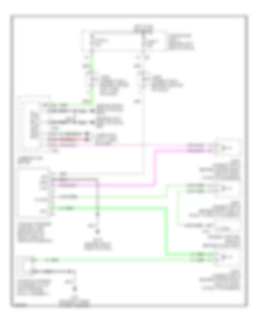
Electronic Power Steering Wiring Diagram for Infiniti Q45 2004
List of elements for Electronic Power Steering Wiring Diagram for Infiniti Q45 2004:
- (behind left side of dash) m24
- (behind right side of dash) m114
- Combination meter
- Computer data lines system
- E24 (on right front strut tower)
- Engine control module (behind glove box)
- F101
- Fuse 7 10a
- Fuse 9 10a
- Fuse block (j/b) 1 (behind left end of dash)
- Gnd
- Hot in on or start
- Ign
- Joint connector 16 (behind upper right end of dash, taped to harness)
- Joint connector 18 (behind upper right end of dash, taped to harness)
- Joint connector 19 (behind right end of dash, taped to harness)
- Joint connector 4 (behind upper left side of dash)
- Joint connector 9 (behind center of dash)
- M114 (behind right side of dash)
- M41
- M43
- Power steering control unit (behind dash, right side of center console)
- Power steering solenoid valve (on steering rack assembly)
- Sol
- Tacho
- Unified meter control unit
- Vsp
 Čeština
 Dansk
Dansk Deutsch
 Ελληνικά
 English
 Español
 Suomi
Suomi Français
 Français
 עברית
עברית Hrvatski
 Magyar
 Italiano
 日本語
日本語 한국어
한국어 Nederlands
 Polski
 Português
 Português
 Română
 Русский
 Slovenčina
 Slovenščina
 Svenska
 Türkçe
 中文 (中国)
 English