ENGINE PERFORMANCE
2.4L
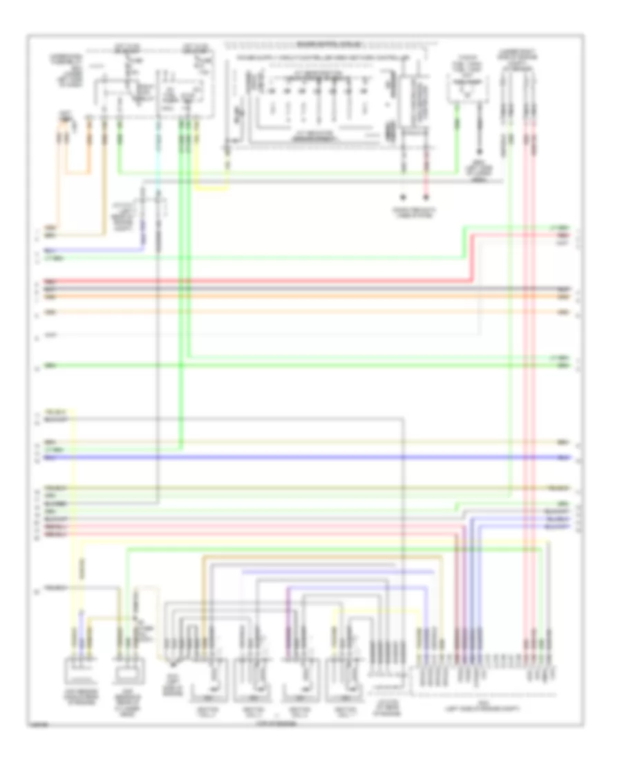
2.4L, Engine Performance Wiring Diagram (1 of 5) for Honda CR-V SE 2011
 https://portal-diagnostov.com/license.html
Automotive Electricians Portal FZCO
Automotive Electricians Portal FZCO
https://portal-diagnostov.com/license.html
https://portal-diagnostov.com/license.html
Automotive Electricians Portal FZCO
Automotive Electricians Portal FZCO
List of elements for 2.4L, Engine Performance Wiring Diagram (1 of 5) for Honda CR-V SE 2011:
- (near fuel tank) evap canister vent shut valve
- (not used)
- A/f sensor relay
- A10
- A11
- A12
- A13
- A14
- A15
- A16
- A17
- A18
- A19
- A20
- A21
- A22
- A23
- A24
- A25
- A26
- A27
- A28
- A29
- A30
- A31
- A32
- A33
- A34
- A35
- A36
- A37
- A38
- A39
- A40
- A41
- A42
- A43
- A44
- A45
- A46
- A47
- A48
- A49
- Acc
- Acpd
- Afshtc
- Air conditioning system
- Anti-theft system
- App sensor (under left side of dash)
- Apsa
- Apsb
- Auxiliary under-dash fuse holder a (under left side of dash)
- B10
- B23
- Bksw
- Bkswnc
- C10
- C11
- C12
- C13
- C14
- Can h
- Can l
- Computer data lines system
- Cooling fans system
- D3sw
- Eld
- Etc2
- Etcs control relay
- Etcsm+
- Etcsm-
- Etcsrly
- F10
- F13
- F16
- F18
- Fanh
- Fanl
- Ftp
- Fuse 15a
- Fuse a 10a
- G101 (left side of engine)
- Hot at all times
- Hot in on or start
- Ig1
- Ig1etcs
- Ignition coil relay
- Igp
- Imo fpr
- Inj1
- Inj2
- Inj3
- Inj4
- Injectors (top of engine)
- J/c c101 (left rear of engine compt)
- J/c c103 (at rear of engine)
- Map
- Map sensor (top of throttle body)
- Mrly
- Navigation & sound systems
- Output shaft (countershaft) speed sensor (on transmission housing)
- Pcm (left side of engine compt)
- Pgm-fi main relay 1
- Pgmetcs
- Pnk
- Pspsw
- Red
- S-net5v
- S1 (thermal joint)
- Scs
- Sg1
- Sg4
- Sg5
- Sg6
- Shift interlock system
- Sls
- Subrly
- Throttle actuator
- Tp sensor
- Tp sensor/ throttle actuator (left rear of engine)
- Under-hood fuse/relay box (on left side of engine compt)
- Used) (not
- Vbsol
- Vcc1
- Vcc3
- Vcc4
- Vcc5
- Vcc6
- Vssout
- Vsv
- Wen
2.4L, Engine Performance Wiring Diagram (2 of 5) for Honda CR-V SE 2011
List of elements for 2.4L, Engine Performance Wiring Diagram (2 of 5) for Honda CR-V SE 2011:
- (not used)
- (top of engine)
- (top of fuel tank) fuel tank unit
- (under right side of engine compt) a/f sensor
- A/t gear position indicator drive circuit
- A/t indicator dimming circuit
- A12
- Afs+
- Afs-
- Area network fast controller
- B12
- C15
- C16
- C17
- C18
- C19
- C20
- C21
- C22
- C23
- C24
- C25
- C26
- C27
- C28
- C29
- C30
- C31
- C32
- C401
- Ckp
- Ckp sensor (middle rear of engine)
- Cmp sensor b (rear of cylinder head)
- Cmpb
- Computer data lines system
- Controller
- Dimming circuit
- Drive circuit
- F10
- F24
- F25
- F30
- Fuel pump
- Fuse 15a
- Fuse 7.5a
- G101 (left side of engine)
- G602 (left side of cargo area)
- Gauge control module
- Hot in on or start
- Icm
- Ig1
- Ig1 fuel pump
- Ignition coil 1
- Ignition coil 2
- Ignition coil 3
- Ignition coil 4
- Igpls1
- Igpls2
- Igpls3
- Igpls4
- J/c c101 (left rear of engine compt)
- J/c c103 (at rear of engine)
- Micu
- Mil ind
- Nca
- P10
- Pcm (left side of engine compt)
- Pgm-fi main relay
- Red
- S3 (ther- mal joint)
- Stabilize 10v
- Stop sw
- Tpsa
- Tpsb
- Under-dash fuse/relay box (under left side of dash)
- Vtc
- Vtpsw
- Warning
2.4L, Engine Performance Wiring Diagram (3 of 5) for Honda CR-V SE 2011
List of elements for 2.4L, Engine Performance Wiring Diagram (3 of 5) for Honda CR-V SE 2011:
- (bottom of radiator) ect sensor 2
- (fuel tank) ftp sensor
- (left rear of engine compt) j/c c101
- (left side of engine) g101
- (not used) c502
- (right side of engine compt) a/c pressure sensor
- (right side of engine compt) psp switch
- (under left side of dash) j/c c404
- (under middle of dash) g503
- (under right side of engine compt) secondary ho2s
- +b horn
- Atp -p
- Atp -r
- B18
- B19
- Brake pedal position switch (under left side of dash, on brake pedal support)
- D3 switch
- D3 switch/ park pin switch (under middle of dash)
- Eld unit
- F15
- F27
- Fuse 10a
- Fuse 15a
- G101 (left side of engine)
- G16
- G302 (under left side of of engine compt)
- G401 (under left side of dash)
- Hot at all times
- Hot in on or start
- Micu
- Oil pressure switch (on right front of engine, above oil filter)
- Red
- Rocker arm oil pressure switch (front right side of cylinder head)
- S1 (thermal joint)
- S3 (thermal joint)
- Shift control solenoid valves
- Starting/ charging system
- Transmission fluid pressure switch a (on transmission housing)
- Under-dash fuse/relay box (under left side of dash)
- Under-hood fuse/relay box (on left side of engine compt)
- Vtc oil control solenoid valve (front of cylinder head)
2.4L, Engine Performance Wiring Diagram (4 of 5) for Honda CR-V SE 2011
List of elements for 2.4L, Engine Performance Wiring Diagram (4 of 5) for Honda CR-V SE 2011:
- (at rear of engine) j/c c103
- (left rear of engine compt) j/c c101
- (on transmission housing) transmission range switch
- A14
- A15
- A16
- A17
- Atf temperature sensor
- B15
- B22
- Ect sensor 1 (rear of engine)
- G101 (left side of engine)
- Iat sensor
- Input shaft (mainshaft) speed sensor (on transmission housing)
- Maf sensor
- Maf/iat sensor (on intake air duct)
- Pnk
- Red
- S2 (thermal joint)
- S4 (thermal joint) (left side of engine compt)
- Starting/ charging system
- Transmission fluid pressure switch b
2.4L, Engine Performance Wiring Diagram (5 of 5) for Honda CR-V SE 2011
List of elements for 2.4L, Engine Performance Wiring Diagram (5 of 5) for Honda CR-V SE 2011:
- (front of engine) knock sensor
- (left rear of engine compt) j/c c101
- (on transmission housing)
- (rear of cylinder head) cmp sensor a
- (rear of engine) evap canister purge valve
- (thermal joint) s2
- A/t clutch pressure control solenoid valve a
- A/t clutch pressure control solenoid valve b
- A/t clutch pressure control solenoid valve c
- A18
- A20
- Altc
- Altf
- Altl
- Atft
- Atp-2
- Atp-fwd
- Atpd
- Atpn
- Atpp
- Atpr
- Atprvs
- Atps
- B10
- B11
- B12
- B13
- B14
- B15
- B16
- B17
- B18
- B19
- B20
- B21
- B22
- B23
- B24
- B25
- B26
- B27
- B28
- B29
- B30
- B31
- B32
- B33
- B34
- B35
- B36
- B37
- B38
- B39
- B40
- B41
- B42
- B43
- B44
- B45
- B46
- B47
- B48
- B49
- Barometer pressure
- C33
- C34
- C35
- C36
- C37
- C38
- C39
- C40
- C41
- C42
- C43
- C44
- C45
- C46
- C47
- C48
- C49
- Cmpa
- Ect1
- G101 (left side of engine)
- Iat
- Lg1
- Lg2
- Lsa
- Lsb
- Lsc
- Op2sw
- Op3sw
- Opsw
- Pcm (left side of engine compt)
- Pcs
- Pg1
- Pg2
- Pnk
- Red
- Rocker arm oil control solenoid (right front of cylinder head)
- S3 (thermal joint)
- Sg2
- Sg3
- Sha
- Shb
- Shc
- Shd
- She
- Sho2s
- So2shtc
- Starting/ charging system
- Starting/charging system
- Vcc2
- Vg+
- Vg-
- Vts

 Čeština
 Dansk
Dansk Deutsch
 Ελληνικά
 English
 Español
 Suomi
Suomi Français
 Français
 עברית
עברית Hrvatski
 Magyar
 Italiano
 日本語
日本語 한국어
한국어 Nederlands
 Polski
 Português
 Português
 Română
 Русский
 Slovenčina
 Slovenščina
 Svenska
 Türkçe
 中文 (中国)