INSTRUMENT CLUSTER
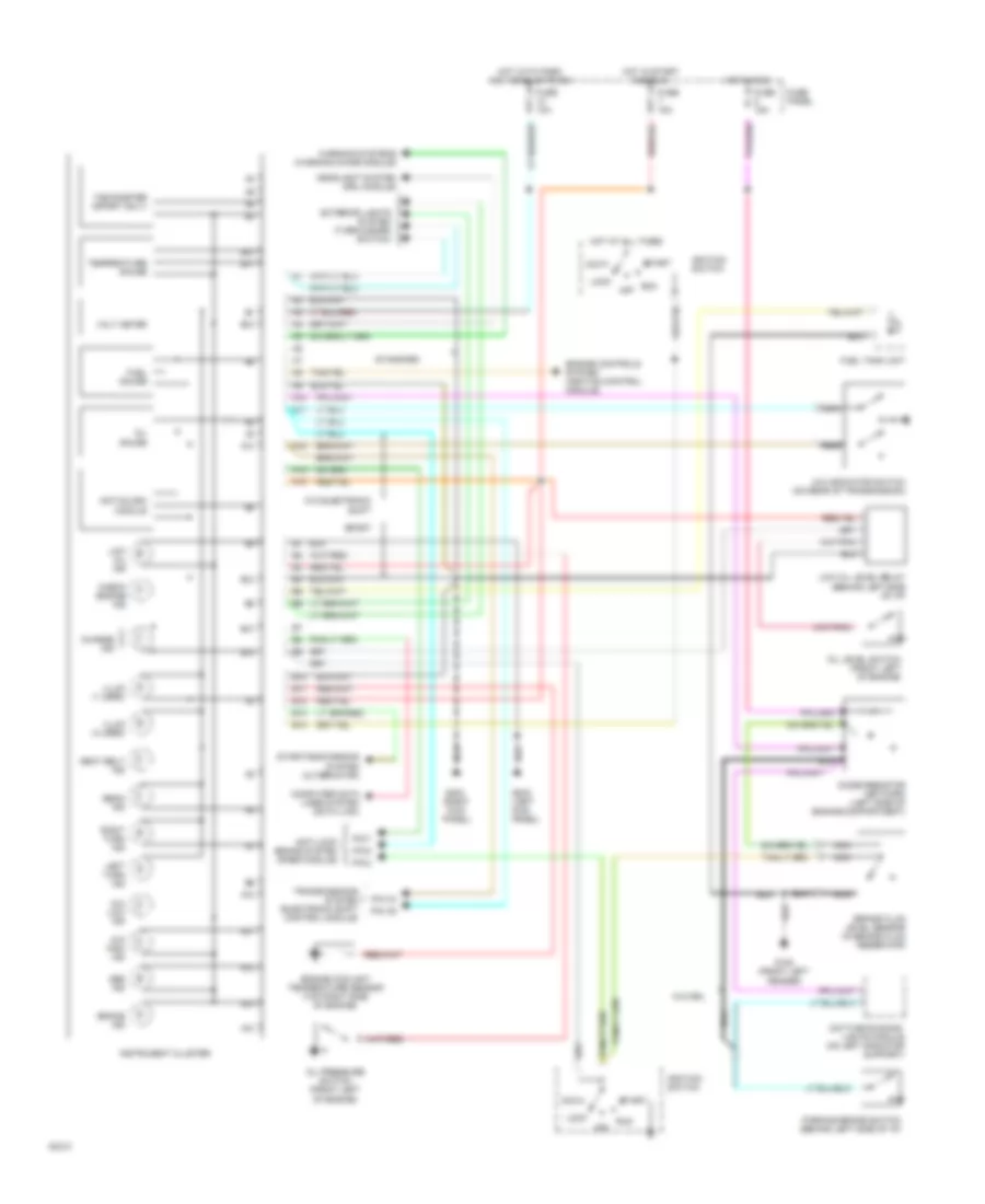
Instrument Cluster Wiring Diagram for Mazda B2300 1994
List of elements for Instrument Cluster Wiring Diagram for Mazda B2300 1994:
- 4x4 high ind
- 4x4 indicator switch (on rear of transmission)
- 4x4 low ind
- A10
- A11
- A12
- A13
- A14
- Abs ind
- Acc
- Anti-lock brake system (rabs module)
- Anti-slosh module
- B10
- B11
- B12
- B13
- B14
- Beam ind
- Brake fluid level sensor (in brake fluid reservoir)
- Brake ind
- Charge ind
- Check engine ind
- Computer data lines system (data link)
- Daytime running lights module (on left radiator support)
- Diode resistor network (left side of engine compartment)
- Engine controls system (ignition control module)
- Engine coolant temperature sensor (top right side of engine)
- Exterior lights system (turn/hazard switch)
- Fuel gauge
- Fuel tank unit
- Fuse 10a
- Fuse 15a
- Fuse panel
- G100 (front left fender)
- G200 (left kick panel)
- G203 (right kick
- Headlight system (drl module)
- Hot at all times
- Hot in run
- Hot in start and run
- Hot with park and headlights on
- Ignition switch
- Illum (1 used)
- Illum (4 used)
- Instrument cluster
- Left turn ind
- Lock
- Low oil ind
- Low oil level relay (behind left side of i/p)
- Nca
- Off
- Oil gauge
- Oil level switch (front left of engine)
- Oil pressure switch (front left of engine)
- Panel)
- Parking brake switch (behind left side of i/p)
- Pin 2
- Pin 5
- Pin 7
- Pin c4
- Pin c5
- Right turn ind
- Run
- Seat belt ind
- Sport
- Standard
- Start
- Starting/charging system (alternator)
- Tachometer (sport only)
- Temperature gauge
- Transmissions system (electronic shift control module)
- Volt meter
- W/o drl
- W/o electronic shift
- Warning systems (warning chime module)
 Čeština
 Dansk
Dansk Deutsch
 Ελληνικά
 English
 Español
 Suomi
Suomi Français
 Français
 עברית
עברית Hrvatski
 Magyar
 Italiano
 日本語
日本語 한국어
한국어 Nederlands
 Polski
 Português
 Português
 Română
 Русский
 Slovenčina
 Slovenščina
 Svenska
 Türkçe
 中文 (中国)
 English