POWER DISTRIBUTION
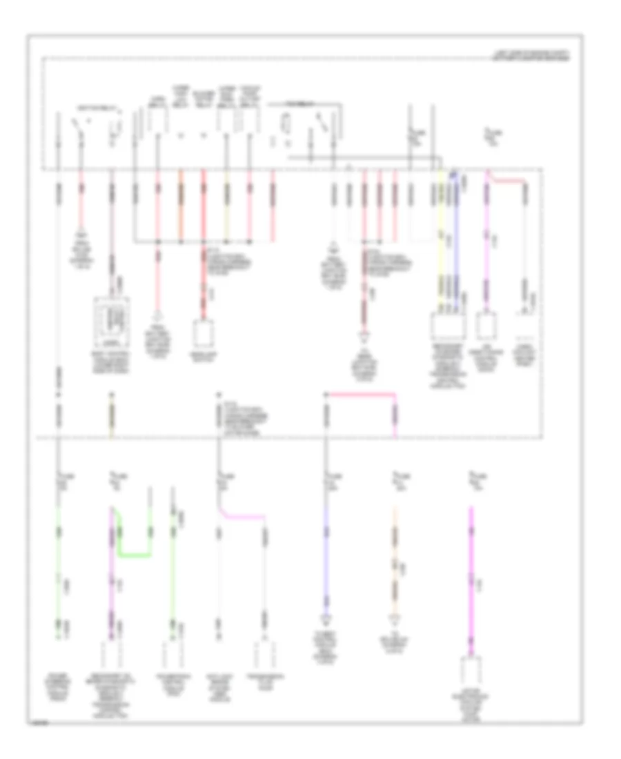
Power Distribution Wiring Diagram (1 of 6) for Ford C-Max Hybrid SE 2014
 https://portal-diagnostov.com/license.html
Automotive Electricians Portal FZCO
Automotive Electricians Portal FZCO
https://portal-diagnostov.com/license.html
https://portal-diagnostov.com/license.html
Automotive Electricians Portal FZCO
Automotive Electricians Portal FZCO
List of elements for Power Distribution Wiring Diagram (1 of 6) for Ford C-Max Hybrid SE 2014:
- (engine wiring harness, near breakout to map sensor) s130
- 150a
- Anti-lock brake system (abs) module
- Battery
- Battery fuse assembly
- Battery junction box (bjb) (left side of engine compt)
- Battery monitoring sensor
- Blower motor relay
- Brake pedal position (bpp)
- C1035c
- C1045
- C140
- C1458a
- C1463a
- C175b
- C4453d
- Charge port light ring
- Coolant water pump 1
- Dc/dc converter module
- Direct current/ alternating current (dc/ac) inverter
- Engine cooling fan relay
- From rear junction box (rjb) (diagram 6 of 6)
- Fuel injector 1
- Fuel injector 2
- Fuel injector 3
- Fuel injector 4
- Fuse 1 80a
- Fuse 10a
- Fuse 15a
- Fuse 2 175a
- Fuse 20a
- Fuse 25a
- Fuse 30a
- Fuse 40a
- Fuse 50a
- Fuse 5a
- G202 (right kick panel)
- G401 (right side of high voltage battery compt)
- High current battery junction box (bjb) (right side of high voltage battery compt)
- Horn relay
- Nca
- Pcm power relay
- Power steering control module (pscm)
- Powertrain control module (pcm)
- Red
- S105 (junction box wiring harness, near breakout to g105)
- S347
- Secondary on board diagnostic module c (sobdmc)/ transmission control module (tcm)
- Switch
- To battery junction box (bjb) (diagram 2 of 6)
- To body control module (bcm) (diagram 4 of 6)
- To body control module (bcm) (diagram 5 of 6)
- To fuse 33 (diagram 3 of 6)
- To splice 115 (diagram 2 of 6)
- To splice s342 (diagram 6 of 6)
- Trans- mission fluid pump
- Vacuum pump cut-off relay
- Wiper run/park relay
Power Distribution Wiring Diagram (2 of 6) for Ford C-Max Hybrid SE 2014
List of elements for Power Distribution Wiring Diagram (2 of 6) for Ford C-Max Hybrid SE 2014:
- (junction box wiring harness, near breakout to g105)
- (left side of engine compt) battery junction box (bjb)
- Air conditioning control module (accm)
- Anti-lock brake system (abs) module
- Blower motor relay
- Body control module (bcm) (lower right side of dash)
- C1035c
- C1046
- C134
- C1458a
- C1463b
- C175b
- C1815c
- C214
- C2280d
- C238
- Cabin coolant heater (phev)
- From battery junction box (bjb) (diagram 1 of 6)
- From splice s105 (diagram 1 of 6)
- Fuse 10a
- Fuse 15a
- Fuse 20a
- Fuse 5a
- Headlamp switch
- Horn relay
- Ignition relay
- Ignition relay control
- Micro
- Motor electronics cooling system pump motor
- Power steering control module (pscm)
- Powertrain control module (pcm)
- Red
- S115 (junction box wiring harness, near breakout to g105)
- S116 (junction box wiring harness, near breakout to blower motor diode)
- Secondary on board diagnostic diagnostic module c (sobdmc)/ transmission control module (tcm)
- Secondary on board diagnostic module c (sobdmc)/ transmission control module (tcm)
- Tcm relay
- To body control module (bcm) (diagram 4 of 6)
- To rear junction box (rjb) (diagram 5 of 6)
- To splice 344 (diagram 6 of 6)
- Transmission fluid pump
- Vacuum pump cut-off relay
- Wiper high/ low relay
- Wiper run/ park relay
Power Distribution Wiring Diagram (3 of 6) for Ford C-Max Hybrid SE 2014
List of elements for Power Distribution Wiring Diagram (3 of 6) for Ford C-Max Hybrid SE 2014:
- (body wiring harness, near breakout to c212) s322
- (engine wiring harness, near breakout to cmp sensor) s132
- (instrument panel wiring harness, near breakout to bcm) s238
- (left side of engine compt) battery junction box (bjb)
- (lower right side of dash) body control module (bcm)
- (not used)
- (roof wiring harness, near breakout to right vanity mirror) s901
- Active grille shutter
- C1035c
- C211
- C2280e
- C2280f
- C238
- C339
- C4198
- C4403
- Cabin heater coolant diverter valve
- Cabin heater coolant pump
- Coil on plug (cop) 1
- Coil on plug (cop) 2
- Coil on plug (cop) 3
- Coil on plug (cop) 4
- Coolant water pump 1
- Driver door window control switch
- Driver side interior lamp (w/ roof opening panel)
- Electric exhaust gas recirculation (eegr) valve
- Engine cooling fan relay
- Evaporative emission canister purge valve
- From fuse 34 m (diagram 1 of 6)
- From fuse 62 l (diagram 4 of 6)
- Front interior lamp (w/o roof opening panel)
- Fuse 10a
- Fuse 15a
- Fuse 20a
- Fuse 5a
- Glove compart- ment lamp
- Heated oxygen sensor (ho2s) 12
- Ignition coil 1
- Left footwell lamp (w/o ambient lighting)
- Left vanity mirror lamp
- Luggage compart- ment lamp
- Nca
- Overhead console switch assembly
- Passenger side interior lamp (w/ roof opening panel)
- Passive anti-theft system (pats) transceiver
- Rear interior lamp
- Right footwell lamp (w/o ambient lighting)
- Right vanity mirror lamp
- S106 (junction box wiring harness, near breakout to c214)
- S119 (junction box wiring harness, near breakout to g104)
- S133 (engine wiring harness, near breakout to knock sensor 1)
- To rear junction box (rjb) (diagram 5 of 6)
- Universal heated oxygen sensor (ho2s) 11
- Variable camshaft timing 11 (vct11)
Power Distribution Wiring Diagram (4 of 6) for Ford C-Max Hybrid SE 2014
List of elements for Power Distribution Wiring Diagram (4 of 6) for Ford C-Max Hybrid SE 2014:
- (body wiring harness, near breakout to g301) s309
- (instrument panel
- (instrument panel wiring harness, near breakout to blend door actuators) s214
- (instrument panel wiring harness, near breakout to glove box lamp) s243
- (lower right side of dash) body control module (bcm)
- (not used)
- Accessory protocol interface module (apim)
- Audio control module (acm)
- C212a
- C212b
- C2280d
- C2280e
- C2280f
- C2280g
- C2280h
- C228b
- C237
- C240a
- C310a
- C311
- C312
- C319
- C3191a
- C3192a
- C380
- Cigar lighter
- Driver heated seat module
- Driver heated seat switch
- From battery junction box (bjb) (diagram 1 of 6)
- From battery junction box (bjb) (diagram 2 of 6)
- Front control/ display interface module (fcdim)
- Front controls interface module (fcim)
- Fuse 10a
- Fuse 15a
- Fuse 20a
- Fuse 5a
- Fuse 7.5a
- G202 (right kick panel)
- Gateway module a (gwm)
- Glass roof panel blind module
- Global positioning system module (gpsm)
- Heating ventilation & air conditioning (hvac) control module
- Instrument panel cluster (ipc)
- Interior light relay
- Liftgate/ decklid release relay
- Micro
- Occupant classification system module (ocsm)
- Passenger air bag deactivation (pad) indicator
- Passenger heated seat module
- Passenger heated seat switch
- Radio frequency (rf) receiver
- Rain sensor
- Red
- Restraints control module (rcm)
- S340 (body wiring harness, near breakout to c311)
- S347
- S356
- Spare relay
- Steering angle sensor module (sasm)
- Telematic control unit module (tcu)
- To c210) s237
- To fuse 60 (diagram 3 of 6)
- Trans- mission control switch (tcs)
- Vpwr
- W/ heated seats
- Wiring harness, near breakout to c210) s236
- Wiring harness, near breakout to g202) s242
Power Distribution Wiring Diagram (5 of 6) for Ford C-Max Hybrid SE 2014
List of elements for Power Distribution Wiring Diagram (5 of 6) for Ford C-Max Hybrid SE 2014:
- (base of left "d" pillar) rear junction box (rjb)
- (instrument panel wiring harness, near breakout to blend door actuators) s231
- (lower right side of dash) body control module (bcm)
- Acc
- Acc run
- Acc/ run
- Battery charger control module (bccm) (phev)
- Battery energy control module (becm)
- Battery junction box (bjb) (left side of engine compt) c1035c
- Body control module (bcm) (lower right side of dash)
- C175b
- C214
- C2280c
- C2280f
- C2280g
- C237
- C315
- C4237a
- C4392d
- C4455a
- C4816a
- Evaporative emission (evap) leak detection control module
- Fhev
- Fog lamp relay
- From battery junction box (bjb) (diagram 1 of 6)
- From splice 106 c (diagram 3 of 6)
- From splice 124 h (diagram 2 of 6)
- Front washer relay
- Fuel door release relay
- Fuel pump relay
- Fuel tank isolation valve (phev)
- Fuse 10a
- Fuse 15a
- Fuse 20a
- Fuse 5a
- High beam relay
- Ignition switch
- Illum
- Key in ign sw
- Key in ignition switch
- Lock
- Micro
- Nca
- Off
- Phev
- Powertrain control module (pcm)
- Rear washer relay
- Red
- Remote function actuator (rfa) module
- Reversing lamp relay
- Run
- S339 (body wiring harness, near breakout to rjb)
- S346 (rear axle wiring harness, near breakout to fuel tank unit)
- Start
- Start/ run
- Start/ stop sw 1
- Start/ stop sw 2
- Transmission control switch (tcs)
- Vapor management valve (fhev)
- W/ intelligent access
- W/o intelligent access
Power Distribution Wiring Diagram (6 of 6) for Ford C-Max Hybrid SE 2014
List of elements for Power Distribution Wiring Diagram (6 of 6) for Ford C-Max Hybrid SE 2014:
- (base of left "d" pillar) rear junction box (rjb)
- (body wiring harness, near breakout to g306) s321
- (body wiring harness, near breakout to rjb) s342
- (instrument panel wiring harness, near breakout to left footwell lamp)
- A14
- A17
- Accessory relay
- B17
- Battery charger control module (bccm)
- Battery energy control module (becm)
- Body control module (bcm) (lower right side of dash)
- Breakout to left rear lamp)
- C211
- C212a
- C212b
- C2280b
- C237
- C2488b
- C311
- C312
- C313
- C314
- C3191a
- C3192a
- C339
- C340
- C4014a
- C410
- C411
- C4174a
- C4237a
- C431
- C432
- C4392c
- C4455a
- C4816a
- C494
- C501a
- C510
- C610
- C652a
- C700
- C800
- Control relay accessory
- Datalink datalink connector connector (dlc) (dlc)
- Digital audio control module
- Driver door module (ddm)
- Driver exterior door handle
- Driver heated seat module
- Driver rear door module (drdm)
- Driver side front seat control switch
- Fhev
- From battery fuse assembly (diagram 1 of 6)
- From battery junction box (bjb) (diagram 2 of 6)
- Fuse 10a
- Fuse 15a
- Fuse 20a
- Fuse 25a
- Fuse 30a
- Fuse 40a
- Fuse 5a
- G304 (base of right "d" pillar)
- Gateway module a
- Glass roof panel blind module
- Handsfree liftgate actuation module (w/ power liftgate)
- High voltage battery charger cooling fan (phev)
- High voltage battery cooling fan
- Left rear exterior door handle
- Luggage compartment power outlet socket
- Micro
- Nca
- Parking aid module
- Passenger door module (pdm)
- Passenger exterior door handle
- Passenger heated seat module
- Passenger rear door module (prdm)
- Phev
- Rear gate trunk module (rgtm)
- Rear parking aid camera module
- Rear window defrost relay
- Rear window wiper motor
- Rear wiper relay
- Red
- Remote function actuator (rfa) module
- Right rear exterior door handle
- S221
- S325 (w/ intelligent access)
- S343 (body wiring harness, near breakout to rjb)
- To direct current/ alternating current (dc/ac) inverter (diagram 1 of 6)
- W/ power liftgate

 Čeština
 Deutsch
 Ελληνικά
 English
 English
 Español
 Suomi
Suomi Français
 Français
 עברית
עברית Hrvatski
 Magyar
 Italiano
 日本語
日本語 한국어
한국어 Nederlands
 Polski
 Português
 Português
 Română
 Русский
 Slovenčina
 Slovenščina
 Svenska
 Türkçe
 中文 (中国)