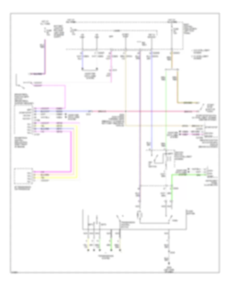
SHIFT INTERLOCK
Shift Interlock Wiring Diagram for Ford Edge Limited 2011
List of elements for Shift Interlock Wiring Diagram for Ford Edge Limited 2011:
- 6f transmission (on transaxle)
- Access
- Battery junction box (bjb) (left side of engine compt)
- Body control module (bcm) (left kick panel)
- Bpp
- Brake pedal position (bpp) switch (brake pedal support bracket)
- Bsi (fet)
- C175b
- C175t
- C215
- C2153c
- C2153e
- C2280a
- C2280b
- C2280f
- C3053
- Can+
- Can-
- Ccb08
- Cdc35
- Computer data lines system
- Control
- Cpk34
- Floor
- Fuse 10a
- Fuse 15a
- G205 (left side of dash)
- Hot at all times
- Hs can +
- Hs can -
- Hs can+
- Hs can-
- Ignition switch (w/o intelligent access)
- Instrument panel cluster (ipc)
- Key in ignition
- Lock
- Micro
- Ms can+
- Ms can-
- Nca
- Park
- Powertrain control module (pcm) (right front of engine)
- Remote function actuator (rfa) module (behind glove box)
- S238 (main wiring harness, near breakout to passive anti-theft restraint module)
- S349
- Shifter
- Sstd
- Sstu
- Start/ stop
- Start/ stop (active hugh)
- Start/stop
- Start/stop switch (w/ intelligent access) (center of dash)
- Switch
- Tr 1
- Tr 2
- Tr 3
- Tr 4
- Transmission
- Transmissions system
- Vdb04
- Vdb05
- Vdb06
- Vdb07
- Vet29
- Vet30
- Vet31
- Vet32
- W/ intelligent
- W/o intelligent
 Čeština
 Dansk
Dansk Deutsch
 Ελληνικά
 English
 English
 Español
 Français
 Français
 עברית
עברית Hrvatski
 Magyar
 Italiano
 日本語
日本語 한국어
한국어 Nederlands
 Polski
 Português
 Português
 Română
 Русский
 Slovenčina
 Slovenščina
 Svenska
 Türkçe
 中文 (中国)
 Suomi
Suomi