TRANSMISSION
3.5L HYBRID
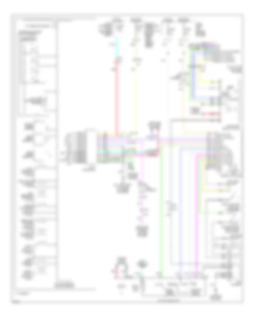
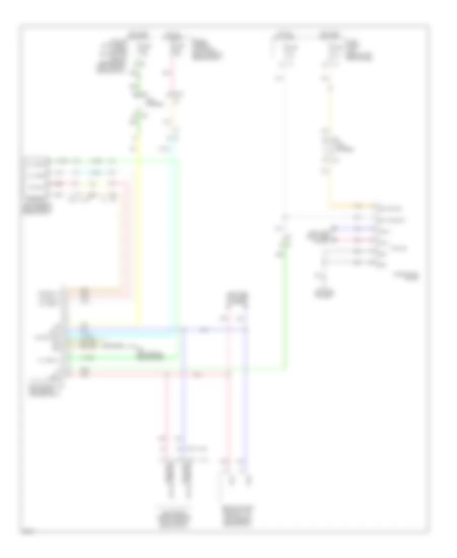
3.5L Hybrid, Transmission Wiring Diagram for Infiniti Q70 3.7 2014
 https://portal-diagnostov.com/license.html
Automotive Electricians Portal FZCO
Automotive Electricians Portal FZCO
https://portal-diagnostov.com/license.html
https://portal-diagnostov.com/license.html
Automotive Electricians Portal FZCO
Automotive Electricians Portal FZCO
List of elements for 3.5L Hybrid, Transmission Wiring Diagram for Infiniti Q70 3.7 2014:
- (left side of dash) m11
- 12c
- A/c auto amp (right end of dash)
- A/t assembly
- A/t fluid temp sensor
- A/t shift selector
- Anti- interlock solenoid valve
- Auto
- Batt pwr sply
- Brake solenoid valve
- Can-h
- Can-l
- Canh
- Clutch 1 solenoid valve
- Combination meter
- Computer data lines system
- Detention switch
- Direct clutch solenoid valve
- Door locks
- Drive mode select switch
- E106
- Eco
- Exterior lights system
- F103
- F58 (front of engine)
- Front brake solenoid valve
- Fuse & fusible link block (on battery positive post)
- Fuse 10a
- Fuse block (j/b) (behind left end of dash)
- Gnd
- High & low reverse clutch solenoid
- Hot at all times
- Hot in on or start
- Ignition sig
- Ill
- Input clutch solenoid valve
- Input speed sensor 1
- Input speed sensor 2
- Interior lights system
- Ipdm e/r (intelligent power distribution module engine room) (right rear of engine compt)
- Joint connector
- K-line
- Line pressure solenoid valve
- Low brake solenoid valve
- M116
- M135
- M201
- M26
- M30
- M95 (right side of dash)
- Manual
- Manual mode
- Mode select switch
- Mode sig
- Output speed sensor
- Pcb harness
- Pnk
- Position select switch
- Pwr sply
- Red
- Select sw (eco)
- Select sw (snow)
- Select sw (sport)
- Select sw (standard)
- Shift dwn sig
- Shift interlock system
- Shift lock unit
- Shift up sig
- Snow
- Sport
- Standard
- Starting/charging system
- Sw1
- Sw2
- Sw3
- Sw4
- System
- Tan
- Tcm (transmission control module)
- Transmission range switch
- Transmission range switch assembly
- Valve
- Vign rev lamp rly can-l start rly
3.7L
3.7L, A/T Wiring Diagram for Infiniti Q70 3.7 2014
List of elements for 3.7L, A/T Wiring Diagram for Infiniti Q70 3.7 2014:
- (left side of dash) m11
- (right end of dash)
- 12c
- A/c auto amp
- A/t assembly
- A/t check ind
- A/t fluid temperature sensor
- A/t shift selector
- Anti- interlock solenoid valve
- Atf pressure sensor
- Auto
- Batt
- Batt pwr sply
- Brake solenoid valve
- Can-h
- Can-l
- Canh
- Combination meter
- Computer data lines system
- Data link connector (lower left side of dash)
- Direct clutch solenoid valve
- Drive mode select switch
- E106
- E20
- Eco
- Exterior lights system
- F103
- F103 m116
- F33 (5.6l: left front of engine) (3.7l: front of engine)
- F40
- Front brake solenoid valve
- Fuse & fusible link block (right rear of engine compt)
- Fuse 10a
- Fuse block (j/b) (behind left end of dash)
- Gnd
- High & low reverse clutch solenoid
- Hot at all times
- Hot in on or start
- Ignition sig
- Ill
- Input clutch solenoid valve
- Input speed sensor 1
- Input speed sensor 2
- Interior lights system
- Ipdm e/r (intelligent power distribution module engine room) (right rear of engine compt)
- Joint connector
- K-line
- Line pressure solenoid valve
- Low brake solenoid valve
- M105
- M116
- M135
- M137
- M181
- M20
- M201
- M202
- M22
- M23
- M24
- M26
- M28
- M30
- M95 (right side of dash)
- Manual
- Manual mode
- Mode select switch
- Mode sig
- Nca
- Output speed sensor
- Paddle shifter (shift-down) (if equipped)
- Paddle shifter (shift-up) (if equipped)
- Pcb harness
- Pnk
- Position select switch
- Red
- Select sw (eco)
- Select sw (snow)
- Select sw (sport)
- Select sw (standard)
- Shift dwn sig
- Shift interlock system
- Shift lock unit
- Shift up sig
- Snow
- Sport
- Standard
- Starting/ charging system
- Sw1
- Sw2
- Sw3
- Sw4
- Tan
- Tcm (transmission control module)
- Torque converter clutch solenoid valve
- Transmission range switch
- Transmission range switch assembly
- Valve
- Vign
- Vign rev lamp rly can-l start rly
3.7L, AWD Wiring Diagram for Infiniti Q70 3.7 2014
List of elements for 3.7L, AWD Wiring Diagram for Infiniti Q70 3.7 2014:
- (3.7l)
- (5.6l)
- (or can comm line)
- 12c
- Abs actuator & electric unit (control unit) (left rear of engine compt)
- Awd control unit (left side of luggage compt)
- Awd ind
- Awd sol (+)
- Awd sol (-)
- Awd sol bat
- Awd solenoid (right rear of engine compt)
- B61 (left side of rear bumper)
- Bat pwr sply
- Can-h
- Can-l
- Combination meter
- Computer data lines system
- E106
- Ecm (engine control module) (right rear of engine compt)
- Ets sol+
- Ets sol-
- F103
- Fuse & fusible link block (right rear of engine compt)
- Fuse 10a
- Fuse block (j/b) (behind left end of dash)
- Gnd
- Hot at all times
- Hot in on or start
- Ign
- Ignition sig
- Ipdm e/r (intelligent power distribution module engine room) (right rear of engine compt)
- M107 (or can comm line)
- M11 (left side of dash)
- M116
- M160
- M22
- M24
- Oil temp (+)
- Oil temp (-)
- Oil temp+
- Oil temp-
- Pcb harness
- Pnk
- Red
- Tan
- Veh can-h1
- Veh can-l1
5.6L
5.6L, A/T Wiring Diagram for Infiniti Q70 3.7 2014
List of elements for 5.6L, A/T Wiring Diagram for Infiniti Q70 3.7 2014:
- (left side of dash) m11
- (right end of dash)
- 12c
- A/c auto amp
- A/t assembly
- A/t check ind
- A/t fluid temperature sensor
- A/t shift selector
- Anti- interlock solenoid valve
- Atf pressure sensor
- Auto
- Batt
- Batt pwr sply
- Brake solenoid valve
- Can-h
- Can-l
- Canh
- Combination meter
- Computer data lines system
- Data link connector (lower left side of dash)
- Direct clutch solenoid valve
- Drive mode select switch
- E106
- E20
- Eco
- Exterior lights system
- F103
- F103 m116
- F33 (5.6l: left front of engine) (3.7l: front of engine)
- F40
- Front brake solenoid valve
- Fuse & fusible link block (right rear of engine compt)
- Fuse 10a
- Fuse block (j/b) (behind left end of dash)
- Gnd
- High & low reverse clutch solenoid
- Hot at all times
- Hot in on or start
- Ignition sig
- Ill
- Input clutch solenoid valve
- Input speed sensor 1
- Input speed sensor 2
- Interior lights system
- Ipdm e/r (intelligent power distribution module engine room) (right rear of engine compt)
- Joint connector
- K-line
- Line pressure solenoid valve
- Low brake solenoid valve
- M105
- M116
- M135
- M137
- M181
- M20
- M201
- M202
- M22
- M23
- M24
- M26
- M28
- M30
- M95 (right side of dash)
- Manual
- Manual mode
- Mode select switch
- Mode sig
- Nca
- Output speed sensor
- Paddle shifter (shift-down) (if equipped)
- Paddle shifter (shift-up) (if equipped)
- Pcb harness
- Pnk
- Position select switch
- Red
- Select sw (eco)
- Select sw (snow)
- Select sw (sport)
- Select sw (standard)
- Shift dwn sig
- Shift interlock system
- Shift lock unit
- Shift up sig
- Snow
- Sport
- Standard
- Starting/ charging system
- Sw1
- Sw2
- Sw3
- Sw4
- Tan
- Tcm (transmission control module)
- Torque converter clutch solenoid valve
- Transmission range switch
- Transmission range switch assembly
- Valve
- Vign
- Vign rev lamp rly can-l start rly
5.6L, AWD Wiring Diagram for Infiniti Q70 3.7 2014
List of elements for 5.6L, AWD Wiring Diagram for Infiniti Q70 3.7 2014:
- (3.7l)
- (5.6l)
- (or can comm line)
- 12c
- Abs actuator & electric unit (control unit) (left rear of engine compt)
- Awd control unit (left side of luggage compt)
- Awd ind
- Awd sol (+)
- Awd sol (-)
- Awd sol bat
- Awd solenoid (right rear of engine compt)
- B61 (left side of rear bumper)
- Bat pwr sply
- Can-h
- Can-l
- Combination meter
- Computer data lines system
- E106
- Ecm (engine control module) (right rear of engine compt)
- Ets sol+
- Ets sol-
- F103
- Fuse & fusible link block (right rear of engine compt)
- Fuse 10a
- Fuse block (j/b) (behind left end of dash)
- Gnd
- Hot at all times
- Hot in on or start
- Ign
- Ignition sig
- Ipdm e/r (intelligent power distribution module engine room) (right rear of engine compt)
- M107 (or can comm line)
- M11 (left side of dash)
- M116
- M160
- M22
- M24
- Oil temp (+)
- Oil temp (-)
- Oil temp+
- Oil temp-
- Pcb harness
- Pnk
- Red
- Tan
- Veh can-h1
- Veh can-l1

 Čeština
 Dansk
Dansk Deutsch
 Ελληνικά
 English
 Español
 Suomi
Suomi Français
 Français
 עברית
עברית Hrvatski
 Magyar
 Italiano
 日本語
日本語 한국어
한국어 Nederlands
 Polski
 Português
 Português
 Română
 Русский
 Slovenčina
 Slovenščina
 Svenska
 Türkçe
 中文 (中国)