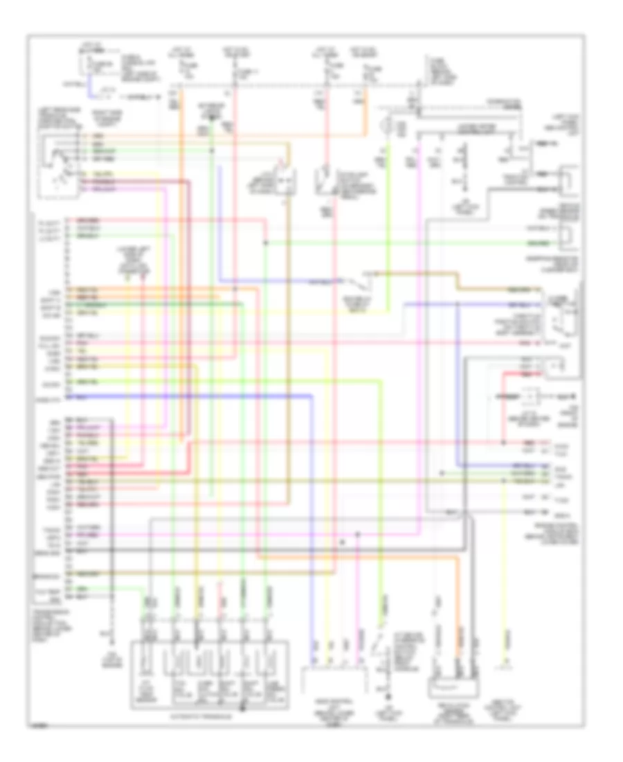
TRANSMISSION
Transmission Wiring Diagram for Nissan Maxima SE 2001
List of elements for Transmission Wiring Diagram for Nissan Maxima SE 2001:
- (left kick panel) abs control unit
- (left rear side trnsaxle) park/neutral position switch
- (lower left side of dash) data link connector
- (right side of engine compt)
- 1-sw
- 10k
- 11k
- 2-sw
- A/t device (overdrive control switch) (below front console)
- A/t fluid temp sensor
- Abs/tcs control unit (left kick panel)
- Acsd
- Acsd 4th
- All times
- Ascd control unit (behind lower center of dash)
- Automatic transaxle
- Avcc
- Brake sw
- Closed throttle
- Combination meter
- D-sw
- Dropping resistor (near air cleaner box)
- Ecm relay (in relay box 2)
- Engine control module (ecm) (behind instrument lower cover)
- Exterior lights system
- F39 (front of engine)
- F42 (top of engine)
- Fld temp
- Full sw
- Fuse & fusible link box (left side of engine compt)
- Fuse 10a
- Fuse 11 10a
- Fuse 15a
- Fuse 59 15a
- Fuse block (behind left side of dash)
- Gnd
- Gnd-a
- Hot at
- Hot in on or start
- Idle
- Idle sw
- J/c 12
- J/c 18 (behind center of dash)
- J/c 3 (behind left side of dash)
- Lan
- Line press sol valve
- Lu duty
- M9 (left kick panel)
- Mem b/u
- N-sw
- Nca
- O/d ind
- O/d off ind
- O/d sw
- Over- run clutch sol
- Ovr/c
- Pl duty
- Pnk
- R-sw
- Red
- Revolution sensor (right rear of transaxle)
- Sen pwr
- Sens gnd
- Shift a
- Shift b
- Shift sol valve a
- Shift sol valve b
- Sss in
- Sss out
- Stoplight switch (on bracket, above brake pedal)
- Tacho
- Tcc sol valve
- Throttle position switch (on throttle body assembly)
- Transmission control module (tcm) (behind lower center of dash)
- Ts in
- Tvo1
- Tvoo
- Unified meter control unit
- Vehicle speed sensor (on transaxle)
- Vign
- Vsp-1
- Vsp-2
- W/ traction control
- W/o
- Wot
 Čeština
 Dansk
Dansk Deutsch
 Ελληνικά
 English
 Español
 Suomi
Suomi Français
 Français
 עברית
עברית Hrvatski
 Magyar
 Italiano
 日本語
日本語 한국어
한국어 Nederlands
 Polski
 Português
 Português
 Română
 Русский
 Slovenčina
 Slovenščina
 Svenska
 Türkçe
 中文 (中国)
 English