TRANSMISSION
Center Differential Lock Wiring Diagram for Toyota Land Cruiser 1996
 https://portal-diagnostov.com/license.html
Automotive Electricians Portal FZCO
Automotive Electricians Portal FZCO
https://portal-diagnostov.com/license.html
https://portal-diagnostov.com/license.html
Automotive Electricians Portal FZCO
Automotive Electricians Portal FZCO
List of elements for Center Differential Lock Wiring Diagram for Toyota Land Cruiser 1996:
- (engine harness, center of safety wall)
- (engine harness, left rear of eng.)
- (i/p harness, right side of dash)
- A/t indicator switch (left side of trans)
- Anti- lock brakes system
- Center differential lock control motor (top of t-case)
- Center differential lock control relay (above left kick panel)
- Center differential lock indicator
- Center differential lock indicator switch (on t-case)
- Conn d
- Diff fuse 30a
- E18
- E22
- Engine control module (right side of dash)
- Fuse block (left side of dash)
- G114 (on air intake chamber)
- G200 (left kick panel)
- Gauge fuse 10a
- Hot in on or start
- I11 (or i12)
- I12 (or i13)
- I6 (or i7)
- I6/i7: i/p harn, left side of dash
- Instrument cluster
- J/c 1 (left side of dash)
- J/c 2 (left side of dash)
- J/c 4 (left dash)
- Neutral detection diode (right side of dash)
- Short pin (center of dash)
- Tfn
- Transfer l4 position switch (rear of trans)
- Transfer neutral position indicator
- Transfer neutral position switch (rear of trans)
Front/Rear Differential Lock Wiring Diagram for Toyota Land Cruiser 1996
List of elements for Front/Rear Differential Lock Wiring Diagram for Toyota Land Cruiser 1996:
- rear differential lock position switch (on rear differential)
- (i/p harness, left side of dash)
- (i/p harness, right side of dash)
- (lower center back panel)
- (or i6) i5
- 4wd
- B25 (or b23)
- C10
- Center diff lock ind
- Center differential lock indicator switch (on t-case)
- Diff fuse 30a
- Differential lock control switch
- Differential lock ecu (behind right i/p)
- Flp
- Front diff lock ind
- Front differential lock control motor
- Front differential lock position switch (on front differential)
- Frt/rr
- Fuse block (left i/p)
- G114 (on air intake chamber)
- G200 (left kick panel)
- G203 (right kick panel)
- G407
- Gauge fuse 10a
- Grd
- Hot in on or start
- I14 (or i15)
- I6 (or i7)
- Instrument cluster
- J/c 1 (left side of dash)
- J/c 8 (right kick panel)
- Rear
- Rear diff lock ind
- Rear differential lock control motor
- Red
- Rel1
- Rel2
- Rel3
- Rel4
- Rlp
- Spd
- Speedo- meter
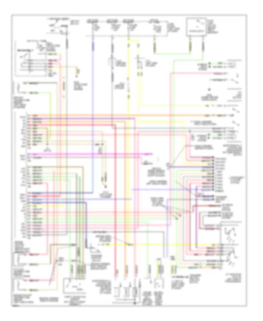
Transmission Wiring Diagram for Toyota Land Cruiser 1996
List of elements for Transmission Wiring Diagram for Toyota Land Cruiser 1996:
- (dash harn, right side of dash) i12 (or i13)
- (dash harness, center of dash)
- (dash harness, left side of dash)
- (dash harness, right side of dash)
- (engine harn, left rear of engine)
- (engine harness, rear of engine)
- (engine harness, right rear of engine compt)
- (or i10)
- (or i7) i6
- 1995,
- 2 indic
- 2nd
- 2nd strt
- A/t fluid temperature sensor (top of trans)
- A/t indicator switch (left side of transmission)
- Acc
- Cruise control ecu (behind left side of dash)
- D indic
- E16
- E18
- Ecu-ig fuse 15a
- Efi fuse 15a
- Efi main relay
- Egr gas temperature sensor (left rear of engine)
- Electronically controlled transmission pattern select switch
- Electronically controlled transmission solenoid (left side of trans)
- Engine control module (behind right side of dash)
- Engine coolant temperature sensor (left side of eng)
- Eo1
- Eo2
- Eo3
- Exterior lights system
- Fuse block (left side of dash)
- G100 (front side of left fender)
- G114 (air intake chamber)
- G302 (under center console box)
- Gauge fuse 10a
- Hold
- Hot at all times
- Hot in on or start
- I11 (or i12) (dash harn, right side of dash)
- I12 (or i13)
- I18 (or i19)
- Idl
- Ign fuse 75a
- Ignition switch
- Igsw
- Instrument cluster system
- Interior lights system
- J/c 1 (left side of dash)
- J/c 4 (center of dash)
- J/c 6 (center of dash)
- L indic
- Mrly
- N indic
- Neutral detect diode (right side of dash)
- No 1
- No 2
- No 3
- O/d indic
- O/d main switch
- Od1
- Od2
- Off
- P indic
- Pwr
- Pwr indic
- R indic
- R/b 2 (front side of left fender)
- Red
- Sp2+
- Sp2-
- Spd
- Speedo
- St1
- Start
- Starting/ charging system
- Stop fuse 10aa
- Stop light switch (brake pedal bracket)
- Stp
- Tfn
- Thg
- Throttle position sensor (on throttle body assembly)
- Thw
- Transfer neutral indic
- Transfer neutral position switch
- Transfer position switch
- Vcc
- Vehicle speed sensor (trans output shaft housing)
- Vta

 Čeština
 Dansk
Dansk Deutsch
 Ελληνικά
 English
 Español
 Suomi
Suomi Français
 Français
 עברית
עברית Hrvatski
 Magyar
 Italiano
 日本語
日本語 한국어
한국어 Nederlands
 Polski
 Português
 Português
 Română
 Русский
 Slovenčina
 Slovenščina
 Svenska
 Türkçe
 中文 (中国)