
 Čeština
 Dansk
Dansk Deutsch
 Ελληνικά
 English
 English
 Español
 Français
 Français
 עברית
עברית Hrvatski
 Magyar
 Italiano
 日本語
日本語 한국어
한국어 Nederlands
 Polski
 Português
 Português
 Română
 Русский
 Slovenčina
 Slovenščina
 Svenska
 Türkçe
 中文 (中国)

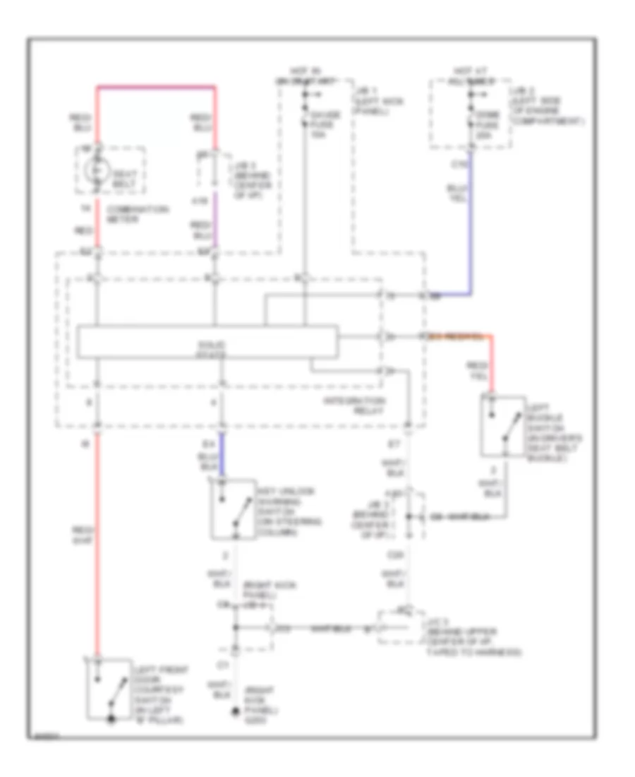
WARNING SYSTEMS
Warning System Wiring Diagrams for Toyota Corolla CE 1997
List of elements for Warning System Wiring Diagrams for Toyota Corolla CE 1997:

AIR CONDITIONINGANTI-LOCK BRAKESANTI-THEFTCOMPUTER DATA LINESCOOLING FANCRUISE CONTROLDEFOGGERSEXTERIOR LIGHTSENGINE PERFORMANCEHEADLIGHTSGROUND DISTRIBUTIONHORNINSTRUMENT CLUSTERINTERIOR LIGHTSPOWER DISTRIBUTIONPOWER DOOR LOCKSPOWER MIRRORSPOWER TOP/SUNROOFPOWER WINDOWSRADIOSHIFT INTERLOCKSSTARTING/CHARGINGSUPPLEMENTAL RESTRAINTSTRANSMISSIONWARNING SYSTEMSWIPER/WASHER